Analog1, Analog1_1
This symbol is used to display analog values with PLC alarms. Please see the description of the Analog1 data point type for a description of the data point elements.
The following panels are available for using analog values:
| Panel | Description |
| Reference editor | Used to create and allocate data points. |
| Equipment operational panel | Allows you to display trends and enter correction values. |
| Trend | Opens the Variable Trend with the specified curve setting. |
| Trend buffer | Allows you to view different values together in a trend display. |
| Information panel | Current data point element values and detailed information on event and details. |
| Simulation panel | Allows you to simulate default values or invalid values. |
| Properties | Used to configure the data point elements (the same panels as under DP Parameters in the Reference panel). |
In order to be able to work with operational and simulation panels (i.e. to simulate a peripheral device), you must first set address activation in the Properties panel and DP Parameters to TRUE. The WCCILsim simulator must also be running.
Reference editor
When you drag the ANALOG1 object out of the STD_OBJECTS catalog into a panel, the Reference editor is opened:
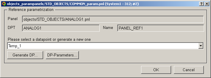
Panel : The top field specifies the object's reference panel.
DPT : Indicates the associated data point type, which is particularly important for symbols with two different data point types (e.g. PUMP1 or PUMP2).
Name : You can give the reference a name used to address it in a script.
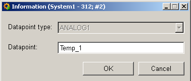
Select a data point from the combo box or create a new data point by pressing Generate DP:
The sample data points of the data point types are not suggested so as to prevent them from being configured. If you try to enter a name that already exists, an error message is displayed.
DP-Parameters opens the panels for configuration (see Properties).
Equipment operational panel Analog1
If you have assigned a data point to the object, after saving you can click on the inserted Analog1 object in Vision. A right mouse click will open a context menu, a left mouse click will open the control panel.
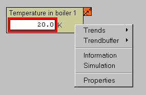
In order to use the panel, you must first activate the addresses in the Properties panel and enter values in the Simulation panel.
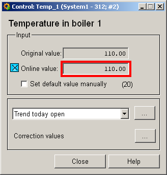
Original and online value are displayed in the top two fields. The red border indicates a triggered alert handling procedure for the online value.
Note that the online value is invalid until a correct online value is set by hand in the simulation panel or supplied by the periphery.
![]() : if the online value is
Invalid, as simulated above, this is indicated by a blue box next to the
online value.
: if the online value is
Invalid, as simulated above, this is indicated by a blue box next to the
online value.
![]() : the default value
can be set by hand, its value is displayed in brackets with an orange box.
: the default value
can be set by hand, its value is displayed in brackets with an orange box.
combo box for selecting the trend display. The "..." button opens the panels of the Variable Trend.
Edit correction values: the "..." button opens the panels for the correction values.
Trends, trendbuffer
In order to view values over time you can display the values (and their compression levels) in different periods:
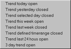
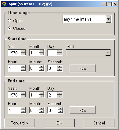
Please see the appropriate chapter of the documentation (Variable Trend) for details on displaying curves as a variable trend. The selection of "Trend defined timerange closed" or "Trend selected day closed " opens the following panel for defining the desired timerange:
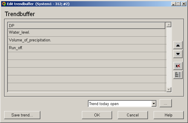
The trend buffer allows you to display different readings together in one trend (e.g.: volume of precipitation, water level, run-off). Right-click on the trend buffer to add a data point (value) to the trend buffer, edit the trend buffer and open the trend buffer (see Working with the trend buffer).
Information panel Analog1
Right-click on the symbol or select theInformation menu to open the following information panel:
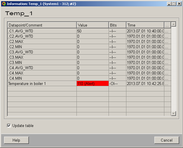
The table contains all data point elements (see data point type ANALOG1), either with their name or description, their values (contents), status (bits) and source time. The "..." buttons open detailed information on event or alert (see alert table).
The panels for the other STD_OBJECTS also contain the corresponding data point elements. For a description of the individual elements, please read the Basics chapter on the data point types of the symbol catalog and the description of the individual data point types.
Simulation panel Analog1
Right-click on the symbol or select theInformation menu to open the following panel for simulating a periphery device. This panel can be used to set data point elements by hand (see Simulating operational states ):
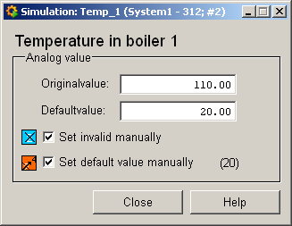
Original and online value are displayed in the top two fields and can be edited.
Invalid bit and default value bit can be set by hand. Note how the appropriate bits are displayed on the symbol.
Properties of Analog1
Right-click on the symbol or select the Propertiesmenu to open the following panel for configuration:
The possible element configs are only displayed on tabs after clicking the individual data point elements (see Configuring objects).
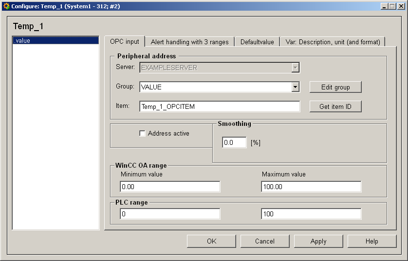
The field on the left contains the data point elements of the associated data point type.
Click on the element to display the tabs used to configure the configs on the right.
You can configure the configs in the right column of the table by clicking on them. Some tabs have text fields for inputting the configuration data.
Because the ANALOG1 data point type only consists of a single element with the appropriate levels of compression, only the .value element can be configured for this symbol. The following table provides a brief description of the tab and links to the related chapters of the Online Help.
| Tab | Description |
| OPC address | Creates the connection to the periphery. Always set address activation to TRUE in order to be able to operate objects! |
| Alert handling | Here you can define limits and text for alert handling procedures. Alert texts can be input in different languages in the Langeditor (click on the line in the table to open). |
| General, Range Default value | Used to define unit, description and default value of a data point element and its WinCC OA value range |
| Smoothing | Enter a tolerance value within which value changes are ignored. |
| Message conversion | Here you can define the edge points for PLC and WinCC OA as minimum and maximum values for an interpolation curve. The values are connected in a linear form. |
Property/configuration panels are also available for all other STD_OBJECTS. Depending on the individual data point elements, different tabs are displayed for configuring the configs.
Please see the appropriate chapters in the PARA module for details on configuring the configs. The Configuring objects chapter describes how to configure a STD_OBJECT.


