Compressor, Fan, Mazerator, Pump - Pump1
These four symbols are assigned either to the data point type Pump1 or Pump2. Pump1 does not allow operation, while Pump 2 can be operated, for example manually. The screenshot shows the symbols in simulated manual operation with maintenance:

Please see the Maintenance package for details on how to monitor maintenance and operating hours with WinCC OA.
Equipment operational panel Pump1
The equipment operational panel displays operational states (On/Off), the mode (remote, local, maintenance, automatic, manual) along with any responses from the PLC and any faults.
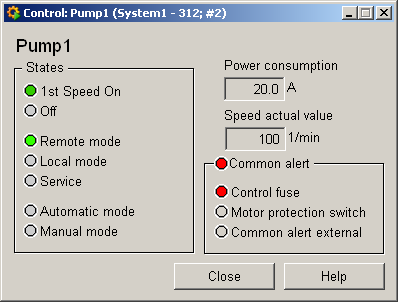
This panel indicates the following details:
-
1. Speed on : The pump is running at the first speed.
-
Off : Grayed out because the pump is running; this box would be green if the pump were switched off.
-
Remote operation : The pump is running in remote mode.
-
Local operation : Grayed out as the pump is active in remote mode.
-
Maintenance : Grayed out, no maintenance is currently taking place. This box would be blue in the event of maintenance. This requires special PLC programming.
-
Automatic mode : The pump is running in automatic mode.
-
Manual mode : Grayed out; blue for manual mode.
-
Current input : 20.0 [A]
-
Currentspeed: 550 [1/min], too high because this value has triggered an alert handling procedure (the box has a red background).
-
Group alert : Active because the control fuse has triggered alert handling.
-
Motor protective switch : Grayed out as there is no fault.
-
Group alertexternal: Grayed out as there is no fault.
If an operating-time counter and operations counter were created for this object, there would be two other buttonsWHandSCthat open the equipment operational panel for the counters (seeMaintenance package).
Information panel Pump1
The information panel contains details on the associated data point elements. Please see the chapter data point types for the symbol catalog (see PUMP1 ) in the PARA module for a description of the data point types and their elements.
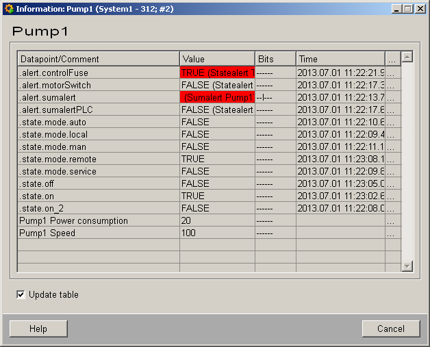
The table contains all data point elements either with their name or description, their values (contents), status (bits) and source time. The "..." buttons open detailed information on the event or alert (see alert table).
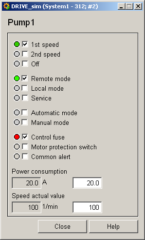
Simulation panel Pump1
Right-click on the symbol or select the Information menu to open the following panel for simulating a peripheral device. This panel can be used to set data point elements by hand. The above equipment operational panel can be displayed with the following inputs in the simulation panel (see Simulating operational states):