Flap, Slide_Valve, Slide_Valve_E, Slide_Valve_P - Slide_Valve2
These four symbols are assigned either to the data point type Slide_Valve1 or Slide_Valve2. If the valves/flaps are not in one of the four possible states, i.e. if the state is undefined, this is indicated by a pale green color.
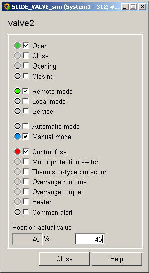
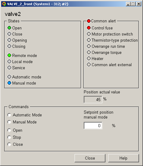
Equipment operational panel Slide_Valve2
The equipment operational panel for data point type Drive2 is more complex. In addition to the operational states there are a number of PLC alerts that display a fault of the respective drive component. Please see the Slide_Valve1 equipment operational panel for a description of the equipment operational panel.
Commands can be sent to the periphery in the bottom part of the panel:
-
Automatic mode , manual mode allow you to switch between modes. In manual mode you can choose between:
-
Opening : Opens valve/flap.
-
Stop : Stops valve/flap movement.
-
Close : Closes valve/flap.
-
Target speed manual mode: Here you can send a desired value to the periphery.
Information panel Slide_Valve2
The information panel contains details on the associated data point elements. Please see the chapter data point types for the symbol catalog (see SLIDE_VALVE2) in the PARA module for a description of the data point types and their elements.
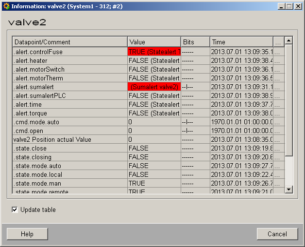
The table contains all data point elements either with their name or description, their values (contents), status (bits) and source time. The "..." buttons open detailed information on the event or alert (see alert table ).
Simulation panel Slide_Valve2
Right-click on the symbol or select the Simulation menu to open the following panel for simulating a peripheral device. This panel can be used to set data point elements by hand. The above equipment operational panel can be displayed with the following inputs in the simulation panel (see Simulating operational states):