Counter1, Counter1_1
As these symbols do not have the usual reference editor, this chapter also describes how to configure Counter1 and Counter1_1. The associated data point type is Counter1. A counter is used to record a quantity per unit of time. Familiar examples include electricity meters, gas meters, etc. which count kW/h or m3per year.
Properties/DP Parameters
It is necessary to specify different addresses depending on the type of counter. We distinguish between three basic types of counter:
-
counter in PLC (normal increment)
-
counter from meter reading (with integral factor)
-
impulse counter (with integral factor)
If the count value or impulses are supplied by the PLC, the panel looks like this:
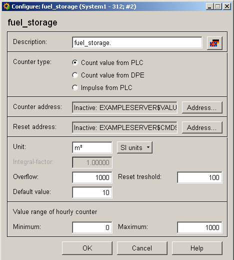
The following settings must be made on this panel:
-
Description: Here you can enter a description of the count value (e.g. amount of fuel, water supply, etc.).
-
Counter type: On the above panel the count value comes from the PLC (raw value is written to the value.plcCounter element). The integral factor field is grayed out in this case.
If the impulses come from the PLC you can specify an integral factor (raw value is written to the .value.plcImpulse element).
-
Counter address: The text box contains the configured OPC address specified on the tab (Address button).
-
Address: This button opens the panel for configuring the OPC address.
-
Reset Address: The text box contains the configured OPC address specified on the tab (Address button).
-
Address: This button opens the panel for configuring the OPC address.
-
Integral factor: Conversion factor for count value from DPE. Used to specify how many of a unit corresponds to one impulse, e.g. let 1 impulse be 1000 liters/h or 1 kW/h, etc.
The counting is only correctly, if the measured value has a unit like something/hour (e.g. m3/h), then the count value is m3.
If e.g. the measured value has a unit liter/second, you have to define the integral factor with 3600, to assure that the count value has the unit liter. If the count value must have a unit m3, set the integral factor to 3,6.
Measured value: unit liter/second; mean of a hour is e.g. 2 > Count value: 2 liter/second*integral factor = 2 liter/second*3600 [integral factor] = 7200 l or = 7,2 m3 with an integral factor = 3,6.
-
Unit: Press this button to select an SI unit or enter one in the text box.
-
Overflow: Specifies the limit as of when counting restarts at zero (e.g. 99999).
-
Reset threshold: Specifies the tolerance range within which a value > 100000 is regarded as an overflow. E.g. let the reset limit be 3000. A value within this reset limit is counted up, e.g. 102500; if the value drops to 96000, it is outside the limit and is counted down (i.e. not counted up to 196000!).
-
Default value: Enter a default value for invalid original values.
-
Range for counted hourly values : Enter the minimum and maximum in the appropriate text boxes. This setting can be useful, for example, to set the value that is possible in one hour within certain limits, e.g. 1000 km/h are not usually possible with a car.
In case the count value is supplied by a data point element, there is a field for selecting the data point element.
-
Source data point: Enter directly in the text box or use the DP selector.
Equipment operational panel
If you have assigned a data point to the object, after saving you can click on the inserted Counter1 object in the Vision module:
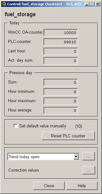
Depending on the type of counter the following inputs are provided:
-
WinCC OA counter : The current count value in WinCC OA.
-
PLC-counter and DP counter: The current reading of the PLC and the data point element.
-
last hourly value : Indicates the last hourly mean.
-
curr. daily total : Indicates the final value of the 1st compression level of COUNTER_SUB.
-
Prev. day : Evaluation of the compression hours of COUNTER_SUB. The following data refer to the 2nd compression level. If compression was not possible, the fields are left at 0 as above. Total: How much was measured, consumed yesterday, in total. Hourly minimum: The smallest hourly value of a reading. Hourly maximum: The largest hourly value of a reading Hourly mean: Mean reading per hour from previous day.
-
Default value set by hand : Default values can be useful in the event of counter failure. If the usual value measured in a given period is known, this figure can be taken as the default value.
-
combo box for trend selection: Select a specified period or press the button to open the Variable Trend panel.
-
Correction values : This button opens the Correction value panel for correcting readings.
If the count value in WinCC OA is supplied by a PLC, this counter can be set to 0 in the PLC by pressing the Reset PLC counter button, both in the PLC and for WinCC OA.
Information panel Counter1
The information panel contains details on the associated data point elements. Please see the chapter data point types for the symbol catalog (see COUNTER1) in the PARA module for a description of the data point types and their elements.
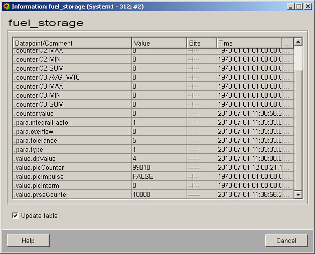
The table contains all data point elements either with their name or description, their values (contents), status (bits) and source time. The "..." buttons open detailed information on the event or alert (see alert table).
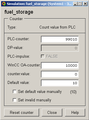
Simulation panel
Right-click on the symbol or select the Information menu to open the following panel for simulating a peripheral device. This panel can be used to set data point elements by hand(seeSimulating operational states).
For example, you can set a different start value to WinCC OA counter from which to start counting resp. reset the counter: