Analog2, Analog2_2, Analog_Bar
ANALOG2 differs from ANALOG1 in that it displays PLC alerts and faults that can be displayed by the appropriate data point elements of the data point type.
The displayed alerts only depend on the PLC limits (para.H1_limit, etc.). Alert handling of the original values is performed in the data point element of the analog value.
For example, you can configure limits for the PLC that prevent or force a pump or valve to switch on. Configuration is done in the PLC.
Equipment operational panel Analog2
Click on the object to open the following equipment operational panel:
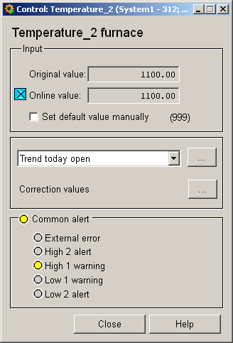
The description of the top area can be found in the Analog1 chapter.
Any PLC alerts are displayed by color changes in the bottom Group alert area on the panel. For example, a limit could cause the PLC to open a valve when a certain pressure, level, etc. has been reached (requires appropriate programming of the PLC).
The group alert is active as soon as a PLC alert has been given (see group alerts).
-
External error : due to error outside the PLC.
-
H2 alarm : if H2 limit of the PLC is exceeded (upper alarm limit)
-
H1 warning : if H1 limit of the PLC is exceeded (upper alarm limit)
-
L1 warning : if value falls below the L1 limit of the PLC (lower alarm limit)
-
L2 alarm : if value falls below the L2 limit of the PLC (lower alarm limit)
Information panel Analog2
The information panel contains details on the associated data point elements. Please see the chapter Data point types for the symbol catalog (see ANALOG2) in the PARA module for a description of the data point types and their elements.
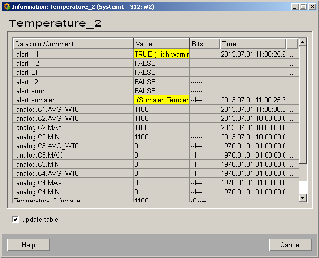
The table contains all data point elements either with their name or description, their values (contents), status (bits) and source time. The "..." buttons open detailed information on the event or alert (see alert table).
Simulation panel Analog2
Right-click on the object and select Simulation to open the following panel with which you can set values and simulate PLC faults (see Simulating operational states):
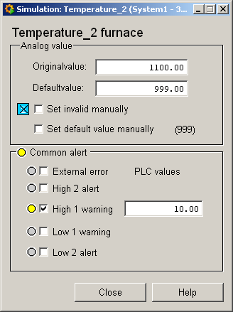
It corresponds to the equipment operational panel except for the text boxes for configuring the PLC limits. The limits specified here are written to the appropriate data point element. Note that an alert handling procedure for the original value of the reading is displayed by a color change regardless of the PLC alerts.


