Working with objects
This chapter presents an example of how to create and configure an object (in this case Analog2), subsequently displaying and operating it with the aid of the simulation panel.
Requirements: WinCC OA has been correctly installed and the STD_symbols are located under Objects in the panel directory.
NG: Open the catalog windows and drag the ANALOG2 object out of STD_OBJECTS and drop it on a panel. Create a new DP.
MG: Click on the panel reference icon and insert the object from the selector. Create a new DP.
 How to insert an object :
-
Select the Analog2 object from the STD_OBJECTS catalog
-
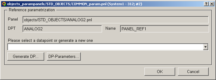
The Reference Editor panel opens automatically:
-
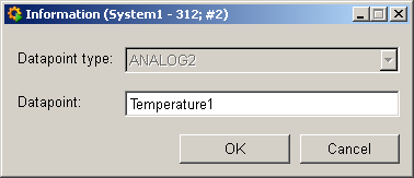
Select a data point from the combo box or create a new data point by pressing"Generate DP...":
-
Your data point is created.
-
The "DP Parameters..." button opens the configuration panels for the data point. You can also open and configure these panels at runtime (see Configuring objects).
-
If necessary, enter a name for the reference in the Reference name field.
-
Click OK to close the reference panel.
You object has now been created and can be operated in Vision; it is ready for use after configuration.
You can test proper functioning and correct configuration of your object with the aid of the simulation panel. Proceed as follows:
How to simulate operational
states and faults
-
Right-click on the Analog2 object and select the Simulation menu item to open the simulation panel.
-
Open the equipment operational panel by left-clicking on the object.
-
At the moment all values are invalid, as indicated by a light-blue check box for the original value and by blue fields for the group alerts.
-
Enter an original value in the simulation panel. The check box for the invalid bit disappears.
-
Click on the radio boxes to trigger all PLC alerts. This activates these alerts in the equipment operational panel.
-
Acknowledge these alerts on the alert panel. In normal state, the fields on the equipment operational panel are gray.
-
Trigger another alert and watch how this triggers the group alert in the equipment operational panel and on the object itself.
You can use the simulation panel to test how the symbols react to periphery alerts.
Working with the trend buffer
The trend buffer allows you to display trend display curves of different data points or objects together
-
Create three objects of the Analog2 type.
-
Configure the objects so as to display, for example, precipitation, temperature and water level.
-
Right-click on the objects and select the Trend buffer > Add to trend buffer menu item to insert them in the buffer.
-
Click Edit trend buffer.
-
Now delete the curves that you do not want to display from the buffer. Select the appropriate curves and click Delete.
-
Press DP Selector to add any other data point elements to the trend buffer to be displayed with the others.
-
Press Display trend buffer or click the "..." button and select a time interval to display the curves (cf. Variable Trend)
-
Click "Save trend" to save your current selection as a new trend configuration. Edit the desired name e.g. climate in the opened dialog and configure the curves as a variable trend.
You can display different readings and their change over time together so as to visualize correlations. The list of trend configurations contains the new configurations.
Of course, you can also create your own objects. The second instructions show how quickly you can accomplish this by using existing objects and panels:
How to create custom standard objects from
STD_PARTS
-
Open the STD_Parts catalog.
-
Create an object using the parts. E.g. a click box with Value, Comment and Unit, etc. similar to Analog1. Enter $dpe+".value" as $parameter for the elements ($dpe).
-
Save the object under MySymbol.pnl in the directory <proj_path/panels/objects/STD_OBJECTS.
-
If you want to use the Reference Editor, save the panel Common_param.pnl in the directory <proj_path/panels/objects. If you want to use your own panel, you must save it as MySymbol_prop.pnl under proj_path/panels/objects_param.
-
Enter a data point type, e.g. DPT_ANALOG1, in the panel properties of the reference under RefDefPanel.
-
Create a new panel and drag your object into the panel.
You custom analog display is finished and available in Vision after saving. It works like the objects defined above (except for invalid and default value, etc.).
When using new DPTs, enter Lib STD_ComplexSymbols.ctl in the "case" instances DPT START and DPT CHANGE "MyTYPE". Only recommended for advanced WinCC OA users!


