Drive, Rotor, Rotor_Big - Drive2
These three symbols are assigned either to the data point type Drive1 or Drive2.

Drive2 can send a number of commands to the periphery.
Equipment operational panel Drive2
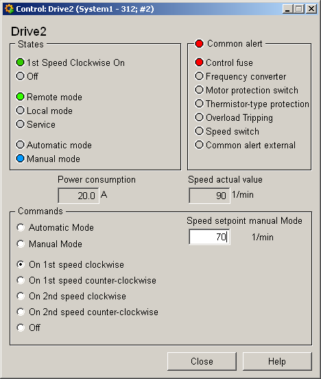
The equipment operational panel for data point type Drive2 is more complex. In addition to the operational states there are a number of PLC alerts that display a fault of the respective drive component. Please see the Drive1 equipment operational panel for a description of the equipment operational panel
Commands can be sent to the periphery in the bottom part of the panel:
-
Automatic mode, manual mode allow you to switch between modes. In manual mode you can choose between:
-
1st speed clockwise: Runs clockwise at first speed.
-
1st speed counterclockwise: Runs counterclockwise at first speed.
-
2nd speed clockwise: Runs clockwise at second speed.
-
2nd speed counterclockwise: Runs counterclockwise at second speed.
-
Off: Switches the drive off.
-
Input of a target speed
Information panel Drive2
The information panel contains details on the associated data point elements. Please see the chapter data point types for the symbol catalog (see DRIVE2) in the PARA module for a description of the data point types and their elements.
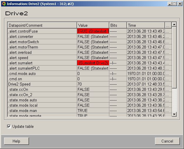
The table contains all data point elements either with their name or description, their values (contents), status (bits) and source time. The "..." buttons open detailed information on the event or alert (see alert table).
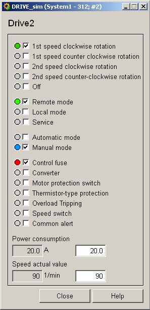
Simulation panel Drive2
Right-click on the symbol or select the Simulation menu to open the following panel for simulating a peripheral device. This panel can be used to set data point elements by hand. The above equipment operational panel can be displayed with the following inputs in the simulation panel (see Simulating operational states):