_cmd_conv, _msg_conv (Conversion)
Depending on whether conversion of variables is from the periphery to the control system (message direction) or, inversely, from the control system to the periphery (command direction), there are two different configs in WinCC OA. The config attributes and conversion modes _msg_conv and _cmd_conv can be found in the Appendix.
-
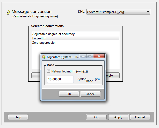
_msg_conv is used to convert data point variables in the message direction.
-
_cmd_conv is used to convert variables sent from the control system to the periphery (=command direction). Original values can be converted in the driver before being forwarded to the periphery.
Because both panels have the same conversion functions, they are described together.
Conversion modes, however, depend on the specific data type of the data point elements. If you want to convert a data point element, a different menu is displayed for the appropriate data point type. These menus are available for the types "unsigned", "integer", "float" and "bool". These menus display configuration panels for the selected conversions.
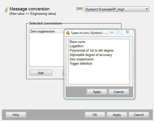
Conversions panel
-
The combo box at the top displays the name (description or alias) of the data point element to be edited.
-
If you want to convert values of a data point element for example in command direction, a menu is displayed for the appropriate data point type by pressing the Add button.
-
Select the desired conversions from these menus: click to select and then press Apply (the figure shows options for the data type float).
-
Select Close to exit the conversion modes menu.
-
From the list Selected conversion modes select a mode by clicking on it.
-
For further configuration click the Properties button. Press Delete to remove a selected conversion mode from the list.
To complete configuration, press OK. Press Apply to save your settings without closing the panel; press Cancel to discard the settings and apply the settings that were active when you displayed the panel.
Different dialog boxes are displayed depending on the calculation. They are detailed below after the conversion types.
Conversion types
Invert
The result is zero if the entry is one and vice-versa (only available for data type bool).
Point curve factor
In order to transfer input values to a point curve factor, the range of values of the data point element is divided into several sections. The edge points of these sections are assigned to fixed output values and linked with linear functions so as to create a continuous curve. It must explicitly assign output values to the input values. The result is a series of straight lines that meet at their ends, the fixed section edges (supporting points), and that share these points. Example: f(x)=x in the range of 0-1, and f(x)=2x-1 in the range of 1-3. Supporting points are (0,0), (1,1) and (3,5).
Logarithm
The output value is the logarithmic input value with a selectable base. Example: f(x)=log10(x)
Polynomials 4th order
The input value can be a polynomial up to the fourth order of the input value with selectable coefficients. Example: f(x)=5x²; the coefficients 0th, 1st, 3rd and 4th order are 0, the coefficient 2nd order is 5.
Adjustable accuracy
The output value is the input value rounded to the selected accuracy. This conversion makes sense in alert direction particularly in combination with old/new comparison type smoothing. By restricting accuracy, you can reduce alerts quite significantly. Example: f(x)=x rounded to 10. The input value 105 appears in the result as 110.
Zero suppression
Input values within a certain range are set to a fixed output value. Example: f(x) = 1 for all 0<x<2. All variable values between zero and two are set to one.
Trigger definition
The output value is one if a limit is exceeded/not reached (the "trigger limit"), otherwise zero.
The configuration menus for conversions in alert direction also offer another operation for input values generated as digital values at the periphery.
Counter impulses
The output value is incremented by one after every increasing or decreasing edge or at each impulse of one or zero.
The possible conversion types depend on the data type!
When converting in alert direction, special care must be taken that the last conversion applied to a variable returns a value that is within the data type range of the variable!
Accuracy
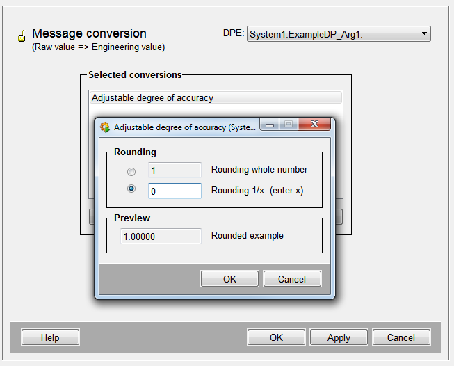
Accuracy dialog box
After selecting Adjustable accuracy, press Properties to open the appropriate panel.
Enter an integer, i.e. for Rounding whole number "1" in order to round to 10.
Enter an integer for the Rounding 1/x , i.e. for Round to the Divisor, e.g. 2, in order to round to 1/2. In the field Rounding 1/x you specify the denominator of the fraction, to which accuracy a number is to be rounded.
Logarithm

Logarithm dialog box
-
Click the above option for natural logarithm.
-
Enter the logarithm base in the field below.
-
Click OK to complete configuration.
Zero suppression
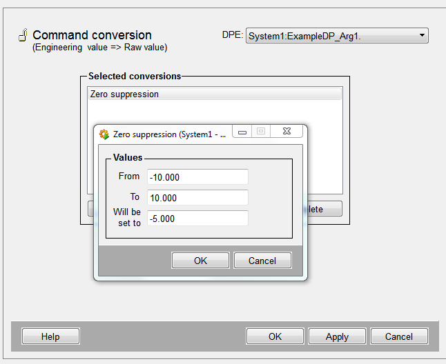
ZERO suppression dialog box
-
Enter the limits of the interval within which to suppress input values ("Values from" / "to").
-
In the next field enter the output value to put in place of the suppressed input values.
Limits and output values must be input as floating point numbers! Thus, if you want to set all values between zero and one to one, enter the limits 0.0 and 2.0, and 1.0 as the output value.
Polynomial
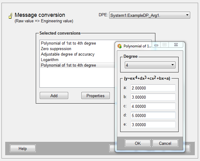
Polynomial dialog box
-
First select an order for the polynomial from the combo box (0-4).
-
Enter the coefficients of the polynomial in the fields below ("a", "b", ...). Depending on the polynomial order, some fields are grayed out.
-
Click OK to complete configuration.
-
Click on the button Cancel to discard your settings; the settings that were active when you displayed the panel are restored.
The coefficients are in descending order. "e" is the coefficient of the fourth order, "d" the coefficient of the third order, etc. For a polynomial that has already been configured, the highest power in it is displayed as the order of the polynomial.
For example, for y = 5x²+x all coefficients disappear except for the first and second order. The order of the polynomial is thus 2.
Base curve factor
Base curve factor dialog box
-
Select the number of a maximum of five supporting points from the combo box at the top.
-
In the next fields ("Supporting point 1" etc.), under "X" enter the range limits of the point curve factor, i.e. the input values that represent the x-coordinates of the interpolation points.
-
In the fields "Y" enter the fixed output values assigned to the x-values, i.e. the y-coordinates of the interpolation points. All interpolation point coordinates must be entered as floating point numbers.
-
Click OK to complete configuration.
-
Click the button Cancel to discard your settings; the settings that were active when you displayed the panel are restored.
Trigger definition
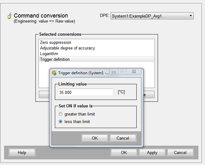
Trigger dialog box
-
In the text field enter the limit at which, if it is not reached/exceeded, you want to set the digital output value to "1". Enter the limit as a floating point number.
-
Click the appropriate option to specify in which of the cases the output value is set to "1" - digital value to 1 if limit not reached or exceeded.
-
Click OK to complete configuration.
-
Click the button Cancel to discard your settings; the settings that were active when you displayed the panel are restored.
Counter impulses
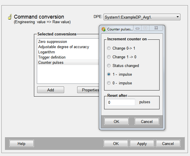
Counter impulses dialog box
In the radio box "Increment counter" click on the appropriate option:
-
"Change 0 -> 1 edge": counts after every increase of the digital value.
-
"Change 1 > 0" counts after every drop of the digital input value.
-
"Status change": counts after every change of the digital input value.
-
"1-impulses": counts input values 1
-
"0-impulses": counts digital input values 0
-
In the text box below the radio box enter an integer indicating after how many impulses to reset the counter.
-
Click OK to complete configuration.
-
Click on the button Cancel to discard your settings; the settings that were active when you displayed the panel are restored.


