Color plant
The plant display Color plant
(<proj_path>/panels/mainpanels/color_plant.pnl)
depicts a simple tank system for lacquer or liquid color production. It is neither
accessible through the "geographical overview" nor through the direct selection buttons
as the first five scenarios are. Select it by clicking in turn Start > Main
screens > Color plant.
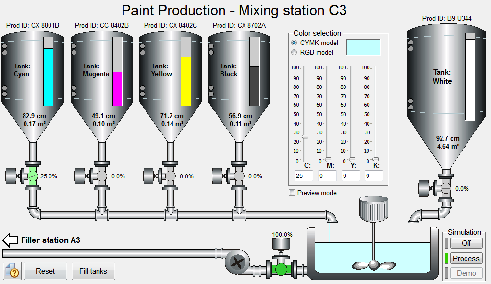
Four containers with liquid base colors and another tank with a neutral white lacquer form the basis of the plant. The spool valve (control valve) at each tank defines the amount of pigment or base color that flows from each tank into the mixing basin.
A Mixer is responsible for thoroughly blending the different colors in the mixing basin. Clicking on the engine case of the mixer activates and deactivates this process. The On-state is revealed through an animation stored as animated GIF file.
GIF stands for Graphics Interchange Format; Animated GIF is an enhancement of the GIF format. Animated GIF allows displaying multiple image files in a sequential and time controlled manner. This produces optically the impression of an animation or a film.
Emptying the mixing container takes place through another slide valve drive and rotary pump. You can also activate the pump drive similar to the mixer by clicking in the operation panel. Again, another GIF animation reveals the On-state.
You can define the required color either with sliders or through the text fields in the color selection dialog to the left of the BASIS tank. You can define the color either according to the CMYK model (CMYK = Color model for color value designation via mixture of turquoise (cyan), magenta, yellow and black) or in the RGB format (RGB = Color model for coloring designation via mixture of red, green and blue). You can change between the two color models at any time. CMYK values lie between 0 and 100 and RGB values between 0 and 255. The selected color is shown directly in the dialog's preview field.
Figure: Color Plant Process Display
Simulation of the color plant
Simulation of the color plant is realized directly in the process display (see also Introduction to simulation). You can choose between three kinds of simulation by clicking the corresponding buttons to the right of the mixing basin in the bottom right corner. The three simulation modes are:
Off:
Only the switch on and off commands for the drives (mixers, pumps) or the manual position commands for the slide valves are processed (this requires the activation of the State signal simulation). The settings in the color selection field are accepted for preview only or, when activated, shown in the mixing basin. No model calculation is made.
Process:
The permanent calculation includes the positions of shut-off valves (slide valves) as well as the levels of containers. Depending on the opening angle of a valve and the level in a tank, more or less color material flows through the pipes. The color flow from the pipe spouts is shown quantitatively and the resulting color can be seen in the mixing basin. The slide valves do not "respond" to changed colors immediately but take into account the runtime of changes in opening angle. Sequence steps must be performed manually.
Demo:
The randomly calculated color batches are produced on an ongoing basis. The runtime operations of single devices is similar to the Process simulation however, sequence steps are automatically executed by the processes. In this way, for example, a full mixing basin is transferred to a bottling plant and the production of another batch is initiated. When raw material in any container runs out, the container is filled again automatically.
When you are running in Demo mode and want to switch to Process mode, you must first change to Off mode.
The simulation operates accurately only when the gate valves of the CMYK raw material tanks are in automatic mode. Clicking the "Reset" button always results in a suitable output mode.
The main purpose of the simulation is to serve as example for demonstrating the graphics capabilities of WinCC OA. It is not intended as an accurate process simulation.
Simple operations
The following actions are possible when working with the process display:
-
With the simulation switched off (Off), click on the mixer and on the pump to manually switch them on or off.
-
Choose or define a color with the sliders.
-
Switch the simulation to Process and observe how the slide valves (the shut-off valves at the tanks) take up the required position. The amount of liquid changes with this as well as the color tone in the mixing tank.
-
Open the equipment operating panel by pressing the slide valve on the BASIS tank and adjust it to any position.
-
Switch on the filler pump (to the left of the tank).
-
Switch off the Process simulation, restart in the Demo mode and observe how new color batches are produced on an ongoing basis.
-
Point the mouse to one of the pipes and see how the current flow rate is displayed in percent (%) of the maximum amount in the tool tip.
Special features
The graphical illustration in the process display "Color plant" has been created with Windows metafiles (see Graphical design of panels). The tanks as well as the pipes and aggregates are based on this vector-oriented graphics format. Animated GIF files were used for some of the animations.
Tanks and sliders are WinCC OA reference objects and thus completely reusable and need little subsequent configuration effort. The calculations for the animations were implemented with the integrated programming script language CONTROL.
WinCC OA can specify the color of graphic objects either by functional color names (color database, see also The Color Editor) or in the RGB code. It is thus possible to display the color in the mixing basin or in the preview window dynamically and continuously. The conversion of the RGB color model into CMYK colors and back has been stored in a panel with local library function.
Associated data point types
Although in this process display large portions of the simulation were created directly in the panel, technological data point types were used throughout for the devices:
-
CP_TANK:Raw material tanks and the mixing basin
-
CP_DRIVE:Mixer and pump
-
CP_SIM:Communication data point for the simulation
-
HVAC_VALVE: Slide valve (Spool valve)


