State signal simulation
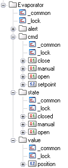
In general, the visualization or process control system sends commands to the peripheral devices. Dedicated command data points are used for this purpose. A changed process state signals a result from such a command which is referred to as a true response. This is usually managed by a further data point element in the process control system. The following data point element example demonstrates this principle:
Figure: Data point with Command structure (cmd) and Responses (State)

The command to open a valve is represented by the data point element .cmd.open. As soon as the valve is fully open, the limit switch is actuated and sends a corresponding response back to the process control system. This operational state can be read from the element .state.open. This operational state will be used for status display in a process display panel.
In order to configure the data point to reflect the original situation as closely as possible, the procedure in this WinCC OA DemoApplication operates as just described. Evaluating the command and returning a corresponding operational response is not implemented here in the simulation script.
The Settings Panel for the simulation allows configuring a delay for the process responses, as in a real world scenario.
Figure: Properties Simulation


