Reaction tank
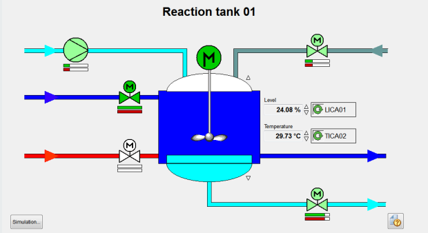
The plant display reaction tank
(<proj_path>/panels/mainpanels/reactor.pnl)
shows a chemical reaction tank with a heat exchanger to guarantee ideal reaction
conditions and thermal stabilization. Open the plant display via the geographical
overview or directly via the direct selection button in the operating block.
The tank R01 is filled with the primary medium via the feeding pump P1 and a control valve. The metering valve V4 registers small amounts of reaction supporting substances. The system P1 - R01- V1 is a continuous process. The agitator M1 ensures thorough mixing of the primary medium and the reactants and takes care of the thermal balance in the tank's content.
The heat exchanger is operated by the controlled inflow of the heating and cooling mediums. The valve V2 regulates the heating medium inflow and V3 determines the inflow of the cooling medium. The mediums are mixed in the heat exchanger which produces a resulting heat exchanger temperature. This temperature influences the reaction tank. The return takes place unregulated, except for a shut-off valve that is not integrated in the automation process.
Procedural boundary conditions dictate that the amount of medium in the reaction tank never falls below a defined minimum level. There is also a maximum filling level. The filling level includes a reserve for expansion of the reacting medium.
The level in the tank is monitored permanently and controlled via the inflow. In addition, there are minimum and maximum alarms for the tank level.
The outflow volume depends on the downstream process and is discontinuous. In the control loop, this is seen as a disturbance.
The reaction tank can be used flexibly for endothermic and for exothermic reactions, as well as for necessary exterior stabilization. The temperature of the reactor content is monitored permanently and is assumed to be almost uniform throughout the medium on account of the agitator M1. The temperature is guaranteed by setpoints controlling the flow valves for the inflow of heating and cooling mediums (V2, V3). The temperature control has a direct influence on the valve V2. The inverse output when controlling V3 is however enforced (for example, V2 = 80 % open then V3 = 20% open).
Simulation
The simulation of the reaction tank is implemented in a Control manager (-f pid_scripts.lst). In the pid_scripts.lst, a script runs for the tank model and another for the reactions of the devices. The regulation is realized in the PID manager (WCCOApid.exe).
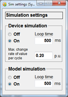
In the following figure, the simulation is started by selecting the option button in the left bottom corner:
Figure: Simulation Settings
The managers have to be started for the operation of the reaction tank and the following entries must be made in the WinCC OA console:
WCCOActrl –num x –f sim.lstThe regulation is executed via the manager (WCCOAPID.exe):
WCCOAPID -num xThese work at the moment only when you have installed the extension<version>. For details on installing demo extensions, see the chapter properties panel.
On: Starts the simulation. ThetankR01 is filled with the primary medium via the feeding pump P1 and the control valve. Theagitator M1takes care of mixing the primary medium with the reactants and ensures the thermal balance in the tank content. The mediums are mixed in the heat exchanger producing a resulting heat exchanger temperature. This temperature influences the reaction tank.
Off : Stops the simulation.
Loop time : Define the loop time in milliseconds.
Max. change rate of value per cycle : Defines how much, at the most, the value may change within a cycle.
Figure: Plant Display, Reaction Tank
![]() The Reglec symbol next to
the level and temperature displays opens the following detailed indicator.
The Reglec symbol next to
the level and temperature displays opens the following detailed indicator.
Figure: TICA02
This indicator displays the actual measured value, defines setpoints directly in the text field or with the slider and adjust the output. In addition, the errors are shown as a percentage.
![]() With this button you
activate or deactivate the regulation. If you deactivate the regulation, manual
operation is activated. When manual operation is activated, you can adjust the
output manually.
With this button you
activate or deactivate the regulation. If you deactivate the regulation, manual
operation is activated. When manual operation is activated, you can adjust the
output manually.
![]() Shows or hides the drag
pointers.
Shows or hides the drag
pointers.
![]() Opens the window shown
below. In this window, you can set the controller parameter and see a trend view.
Different controller settings were created and saved for the PID controller. The
controller settings are LICA configurations. These show the functionality of the
controlled system and the influence of the different controller parameters on the
control system's behavior.
Opens the window shown
below. In this window, you can set the controller parameter and see a trend view.
Different controller settings were created and saved for the PID controller. The
controller settings are LICA configurations. These show the functionality of the
controlled system and the influence of the different controller parameters on the
control system's behavior.
Figure: Controller Settings - TICA02
You can select the different LICA configurations from the combo box next to the save
symbol. Then press ![]() and confirm your
selection.
and confirm your
selection.
![]() Saves a configuration.
Saves a configuration.
![]() Deletes the chosen
configuration.
Deletes the chosen
configuration.
In the upper part of the panel you can start the control system display and view it. You can use the following buttons for viewing the display.
![]() Starts and stops the
display.
Starts and stops the
display.
If you stop the display you can view the trend closer with the aid of the following buttons:
![]() Moves the timeline
backwards.
Moves the timeline
backwards.
![]() Moves the timeline
forwards.
Moves the timeline
forwards.
![]() Allows to scroll the values
downwards.
Allows to scroll the values
downwards.
![]() Allows to scroll the values
upwards.
Allows to scroll the values
upwards.
![]() Restores the normal size of
the display.
Restores the normal size of
the display.
The following buttons can be used when the display is running:
![]() Changes the scaling of the
axis.
Changes the scaling of the
axis.
![]() Shows or hides the value, temperature
and output scales.
Shows or hides the value, temperature
and output scales.
![]() Enlarges the trend
display.
Enlarges the trend
display.


