Standard Symbols
The easiest way to create a graphical user interface is to use ready symbols (references). In WinCC OA, several of those objects are provided. The objects can be used as an aid for the first steps and can also be used as examples for own designed symbols.
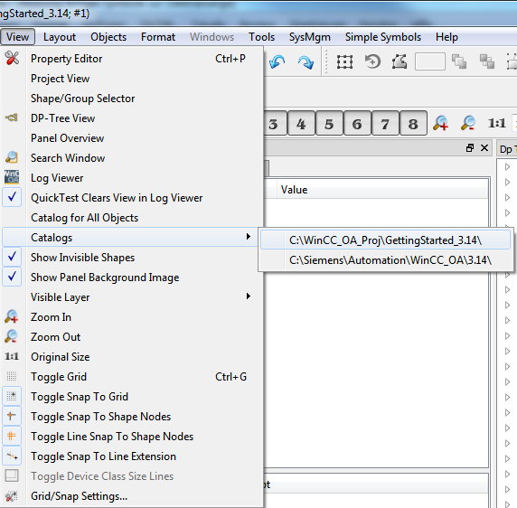
Open the catalog view of the provided graphic objects through the Viewmenu-> Catalogs>C:/Siemens/Automation/WinCC_OA/3.18 (if you have selected another program directory, select the path, see directory structure)
 EXAMPLE
-
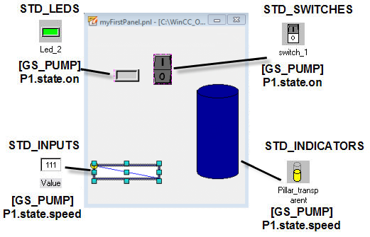
Create a new panel and save it as "myFirstPanel.pnl".
-
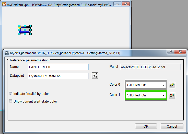
Select the standard symbol "Led_2" from the catalog "STD_LEDS" and drag it to the top left of the drawing area.
-
In th configuration dialog, click on the data point selector button
 .
. -
In the opened data point selector, navigate in the tree view to the element GS_PUMP > P1 > state > on and click on OK.
-
The selected data point element P1.state.on will be added to the input field data point.
-
Remove the checkmark of the check box "alert state color".
-
Click OK in the configuration dialog for Led_2.
-
Make the added symbol Led_2 bigger with the mouse.
The created panel can now display the operating state ON of the pump P1 in form of stylized signal lamp. In order to change this value also directly in the panel, an input element will be added. Additionally the current value of the rotation speed will be shown as a pillar. You can also enter this analog value into a text field.
EXAMPLE
-
Add the symbol "Switch_1" from the "STD_SWITCHES" catalog next to the led.
-
As before, select P1.state.on in the "data point" field.
-
Add the standard symbol "Pillar_transparent" from the catalog"STD_INDICATORS" to the panel down right.
-
Enter the element P1.state.speed for the data point in the configuration dialog.
-
Add also the standard symbol "Value" from the catalog "STD_INPUTS" next to the pillar.
-
Enter the element P1.state.speedlike before for the data point in the configuration dialog.
The input field "Data point" of the configuration dialog for all four used standard symbols contained the text "$dpe_value". This is a so-called "$ parameter" and will be described in the chapter Creating a Device Symbol (Reference). The first part specifies the data type of the expected input and the second part the type of the demanded information.
$dpe_value > dpe … Data point element
value … value
You have to enter the name of the data point element whose current value should be displayed using the standard symbol.
All provided standard symbols are located in the sub directory of the
.../panels/ directory in the installation directory. The graphical
catalog view in the GEDI builds in each case the first level of the sub directories in
the directory <wincc_oa_path>/pictures/panels/objects/.


