Task - Exercise project
All work steps will be explained via small examples in order to keep the projection sequences of WinCC OA as practical as possible. The end result looks like this:
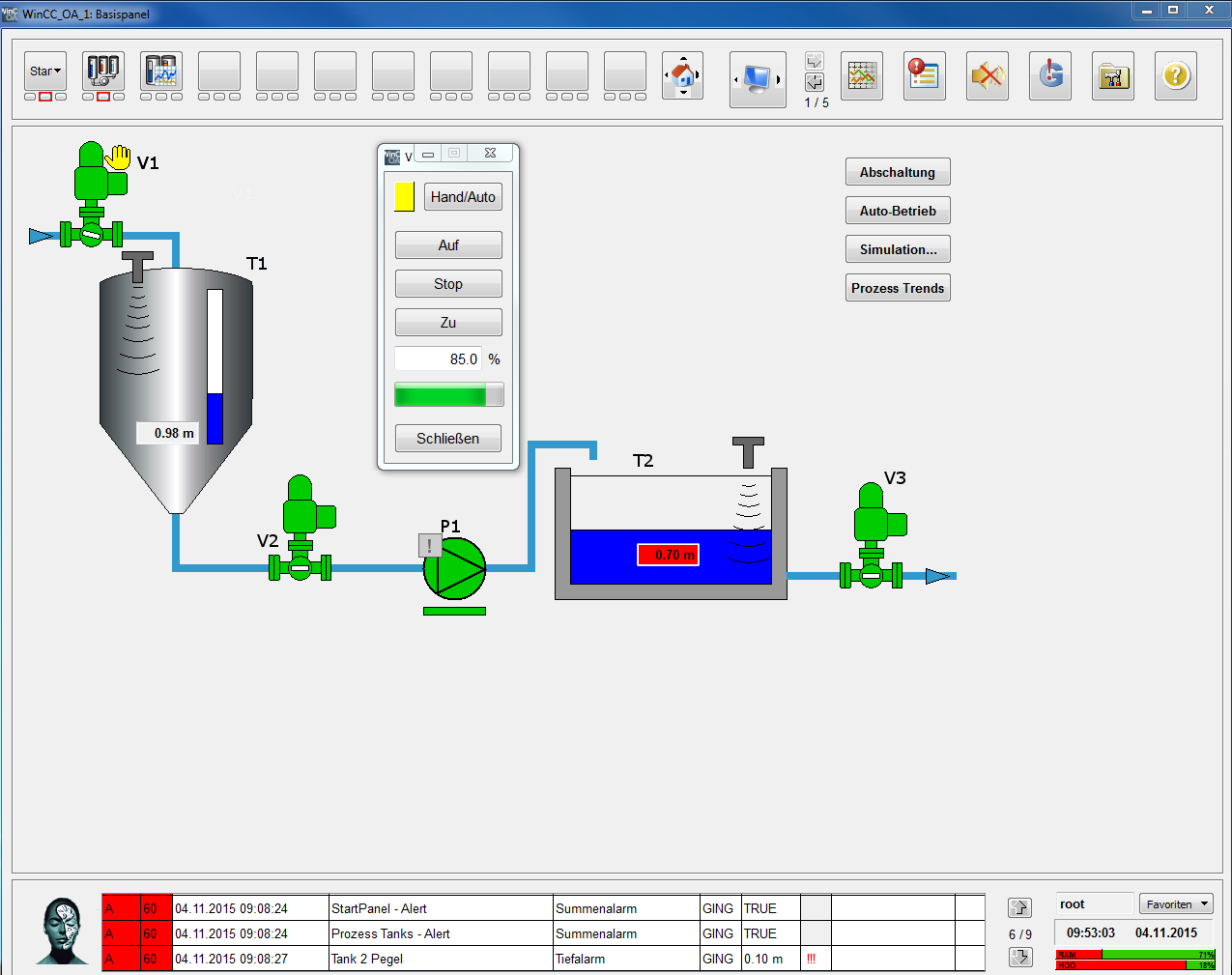
The core of our application is a small tank system. The first tank (T1) is filled through a feed valve (V1). The liquid medium is transferred to an open reservoir (T2) by a second valve (V2) and a pump (P1). The outflow of the reservoir (T2) is controlled by another valve (V3). The procedural sense of the configuration is not considered. The primary goal of this example is to learn the modeling of devices in form of structured data points and to prepare these devices graphically for the use.
At first, we have the following devices:
| Device type | Number | Device (instances) |
|---|---|---|
| Pump (rotation speed variable / FU) | 1 | P1 |
| Fill level sensors (level measurement) | 2 | T1, T2 |
| Engine operated shut-off valve (valve, slider) | 3 | V1, V2, V3 |
Pump ( GS_PUMP)
It should be possible to switch between manual operation and automatic operation for the pump P1. In the manual operation it's possible to specify the rotation speed between 0...100 (in %) and to switch the pump on and off. The operating state (running, stopped, rotation speed, manual operation) as well as a possible alarm should be displayed for the user.
Fill level sensor ( GS_LEVEL)
The fill level sensor provides an absolute level in meters. In addition to the automatic value range monitoring, the user should also be alarmed in case of a too low or too high fill level. Although the tank T1 and the reservoir T2 are designed differently, the level can be measured identically.
Shut off valve ( GS_VALVE)
It should be possible to switch between manual and automatic operation for the valves (slider). The commands On/ Stop/ Off as well as a specification of the opening level should be possible in the manual mode. The valves should show the operating status (end positionopen, end position closed), the current opening level in %, manual operation and a possible alarm.
All commands should be entered using own dialogs, starting from the device symbol (two-stage operation). The properties of these devices correspond approximate to the following simplified measuring/message list. The necessary information is repeated later by numerous step by step instructions.
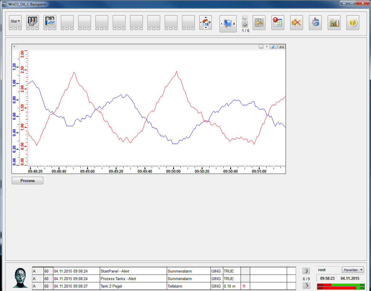
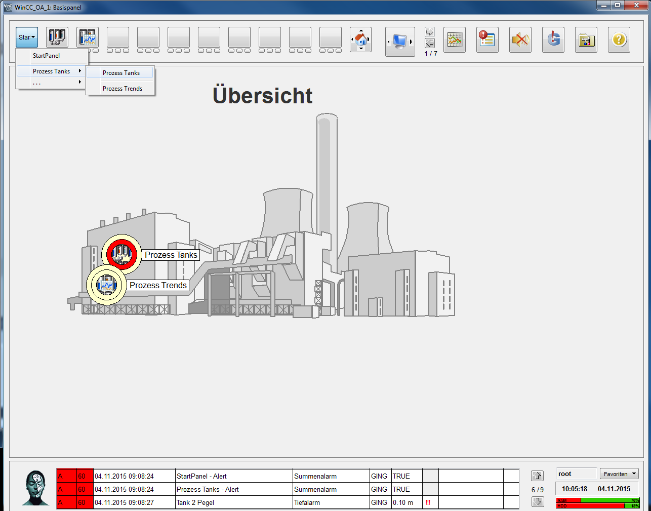
The figures of the devices as well as their operation dialogs are modeled as reusable objects in WinCC OA. The created process image should be included in a superior, flexible configurable operation image. In addition to the process image, a detailed image should show the chronological sequence of the levels in T1 and T2 also graphically (trend). An overview image should facilitate the navigation to the process image (tanks) as well as to other further parts of the plant.
Identifier in WinCC OA depend on the exact notation including upper and lower case (case sensitivity). This applies to data point (element) names as well as variable identifiers or the names of graphic objects (buttons, lines, ....). Consider that all names correspond exactly to the notation specified here, since prepared application parts are used later and these have to suitable for your objects/names.
Prepared Simulation programs that can be simply included in the self created application, enable a simple use with confirmations even without connection to a real process.
The complete configuration exercise project is also available as the application GettingStarted_3.18. If necessary, you can reconstruct some steps using the ready application or also adopt parts of it.


