Input Dialog for Reference
The valves should be operated in a separate dialog like the pump1. You can create it the same way as the reference object itself once for all valves. The principle of placeholders is also applied so that you can create the dialogs exactly the same way as for the reference objects.
In order to test our work steps easier we will integrate the data point monitor in the valve reference. The window of the data point monitor shall be opened through [rightMouseClick] on the valve graphic (for the exact process, see also the figure on the pageDialogs for Graphic Object: Test panel).
-
Select the rectangle with the valve graphic in the reference panel
.../panels/objects/GS_VALVE_ref.pnl. -
Open the wizards for simple configuration in the property sheet ("Standard" tab) for the RightMousePressed event.
-
Select "Panel functions" and confirm with Next>.
-
Select "Open panel (possibly in a new module)" and confirm with Next>.
-
Then open the panel selection dialog with the Open symbol top right.
-
Select the version directory (e.g. C:/Siemens/Automation/WinCC_OA/<version>/panels) from the combo box of the file selection dialog.
-
Select the
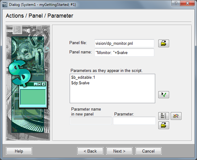
.../vision/dp_monitor.pnlfileand click onOpen. -
Enter the string"Monitor: "+$valve in the field Panelname.
-
Click in the selection list of the parameters on the first entry and enter "1" or "TRUE" for the $b_editable in the field under it. Confirm the assignment by clicking the green checkmark.
-
Click in the selection list of the parameters on the second entry and enter for $dp in the field under it $valve. Confirm this assignment by clicking the green check mark. Now click onNext to proceed to the next step.
-
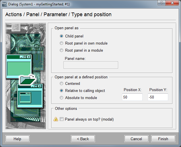
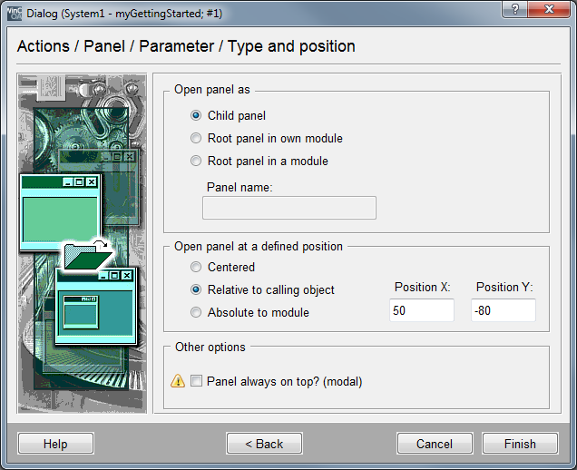
Configure the further call options as shown in the following figure.
If you like, you can also set the data point monitor additionally for the text fields for the level display of the tanks T1 and T2. The only difference is that you have to assign the data point names 'T1' or 'T2' to the $parameter of the calling panel instead of assigning the $ parameter $valve.
The designing of the input dialog for the valves is similar to that of the pump. You merely have to add placeholders in the form of $parameters to the identifiers (data point addresses). When opening the dialog, the calling reference then passes the value for the $ parameter to the dialog.
In the following you can find the rough work steps (not a detailed description):
-
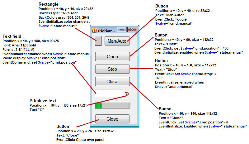
Create a new panel with the size of 132x300 pixels and save it under .../panels/objects_parts/GS_VALVE_dialog.pnl in the current project directory.
-
Draw the buttons, the rectangle, the text field and the primitive text as shown in the figure. Enter "%" for the text value of the format display.
-
Configure a color change to yellow for the rectangle on the top left when the data point element $valve+".state.manual" is set (initialize).
-
Configure a toggle of the value $valve+".cmd.manual" for the hand/auto button when clicked.
-
Select the buttons Open, Stop, Closeand the text field together.
-
Configure the selected group for the initialize event that the objects will be enabled only when the $valve+".state.manual" equals "TRUE" or "1". Override the group selection by selecting another object.
-
Configure the buttons for the clicked event that following default values will be set: button Open $valve+".cmd.position" = 100; button Stop$valve+".cmd.stop" = TRUE, buttonClose $valve+".cmd.position" = 0.
-
Select the text field and configure for initialize that the value of the data point element $valve+".cmd.position" will be shown.
-
Configure the text field also that for EventCommand the current input value will be passed to the data point element $valve+".cmd.position".
-
Configure the button Close that the current panel should be closed. Enter the name "InputSetpoint" for the graphic object (you can set the name of a graphic object using the property "Name" in the property sheet).
-
Save the created panel.
If it should be possible to open the input dialog by using the valve displays, you have to set this for the reference object. The panel should be opened with a [leftMouseClick] on the range of the valve graphic. Therefore, switch to the valve reference object (panels/objects/GS_VALVE_ref.pnl) or open it in the graphic editor.
-
Select the rectangle with the valve graphic.
-
Switch to the properties window, Standard tab and click on the white range next to clicked.
-
Select the option "Panel functions" and click on Next>.
-
Select the option "Open panel (if necessary in a new module)" and click on Next>.
-
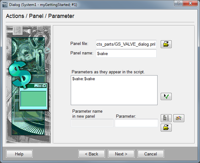
Select the created panel file
.../panels/objects_parts/GS_VALVE_dialog.pnlin the current project diectory. -
Enter $valve in the field panel name - at runtime, the data point name will be shown in the title bar of the dialog (e.g. V2).
-
The list of the $ parameters that exist within the dialog, only comprises an individual parameter $valve. The panel expects to receive the data point name that should be handled using the dialog. The calling reference uses a $parameter with the name $valve as well - this has exactly the same meaning. You can therefore leave the default configuration. Confirm this by clicking the green checkmark. When the panel is called, the reference passes the content of "its" $ parameter $valve (e.g. V2) to the parameter $valve of the calling panel.
-
Complete this step with Next and enter the desired parameter for opening the dialog. Finish the input by clicking the button Finish.