Simple Draw Operations
By selecting a graphic object from the objectbar and dragging a line or a range on the panel area, an object will be added. The following figure describes the available primitive graphic objects and widgets (complex graphic objects) for user interface design.


For detailed information on the graphic objects, see chapter The toolbars.
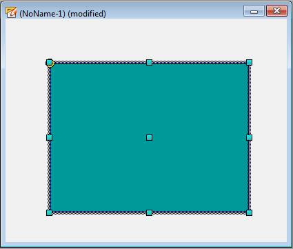
After creating the graphic object, the graphic object will remain selected automatically. In order to select another object simply click [leftMouseClick] on the desired object. A selected object is identified by green, rectangularselection elements around its outline.
To resize an object, drag the selection elements into desired direction with the
mouse. If you move the mouse pointer over the inner part of the selected graphic object,
WinCC OA automatically switches to the "move" mode: when the mouse
pointer shows a ![]() , you can move
the graphic object on the panel area (in case of forms with transparent background by
dragging the frame).
, you can move
the graphic object on the panel area (in case of forms with transparent background by
dragging the frame).
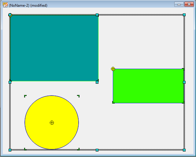
In order to select several objects, hold the shift key after selecting the first object and select the further objects by clicking [leftMouseClick].
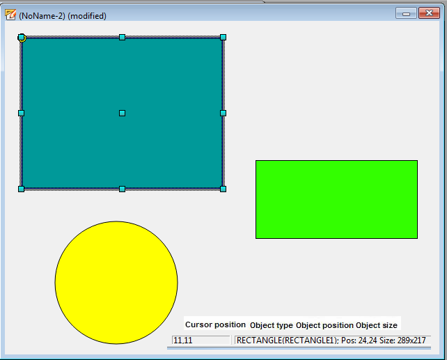
During selection and drawing, you can see the object position and object size in the status bar down right in the GEDI window.
The coordinate system corresponds to the Windows standard: the origin (0,0) is located in the top left corner of the panel. Positive X coordinates ascend to the right, positive Y coordinates ascend from top to the bottom. Positive rotation angles refer to mathematical positive rotation direction (anti-clockwise). For practice, draw some graphic objects in a new panel and try to resize them, move them, change the color and alignment etc.
 EXAMPLE
-
Draw a shape with the rectangle element (object bar).
-
Select the shape with the mouse and move it.
-
Alternatively use the arrows keys [ß], [á], [à], [â] of your keyboard in order to move a selected object. The object will be moved by one pixel every time one of those keys is pressed. When you also hold the [SHIFT] key it moves by a grid division. Note that you have to set the grid/snap settings. Activate the grid/snap option through the view menu.
If a panel is zoomed with less than 100% it is not possible to move selected objects by one pixel.
-
Click on the green selection elements with the mouse and drag in the shown directions - the object size will be changed.
-
To select another background color for an object, click the option background color of the "format" property sheet when the object is selected.
-
To select another foreground color for an object, click the option foreground color of the "format" property sheet when the object is selected.
-
Click the tool
 to select
another line size or another line style.
to select
another line size or another line style. -
Try similar steps independently.
-
Now it's possible to display the result of your work in the runtime view. Using the
 symbol or the menu
Panel -> Save and Run in QuickTest Module, you can opena
previewof what the panel will look like in the runtime user interface.
Name the not yet saved panel "test1.pnl" and save it under
symbol or the menu
Panel -> Save and Run in QuickTest Module, you can opena
previewof what the panel will look like in the runtime user interface.
Name the not yet saved panel "test1.pnl" and save it under
.../panels/(see alsoPreview in the Graphic Editor).
To create a rectangle with same X and Y length, meaning square, hold the SHIFT key while dragging. When holding the SHIFT key you can keep the proportionality of the object.
When drawing a polygon, hold the mouse buttonuntil the second point of the line and click for the further points. The geometry of created polygons can be changed through the Layout menu -> Edit Mode.
The purpose of this tutorial is not to describe the tools of the graphic editor in detail. You will learn the most important functions with the help of some examples. For more information, see the chapter Module GEDI, Basics of the online help.


