Initialize/Change color
The color of the object (foreground and background or both) will change to the defined color when the value of the selected data point is too high or too low. You can, for example, use up to five color changes per DPE.
The color change can be any of the following:
-
Background and foreground can be changed separately or together.
-
based on an alert handling whose thresholds and alert colors are defined in the PARA module using the data point config alert handling. (See Module PARA/Data point configs)
-
or based on changes of specific values. In this case you must also define the thresholds and colors using Simple Configuration (in addition to the appropriate DPE).
Change color based on an alert handling
 Example
-
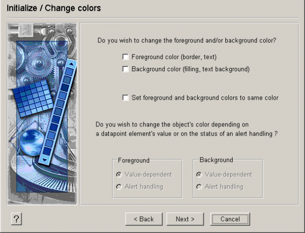
Select an object, for example, an ellipse and click on the Open property wizards button.
-
The Initialization window opens. Select the Change color option.
-
In the Initialize/Change colors panel select the check box Background color(filling, text background).
-
The radio box Value-dependent is selected automatically in the lower part of the panel.
-
Click on Next >. The next panel is opened.
-
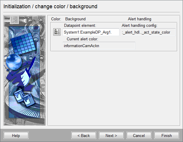
Select the data point whose value change should cause the color change.
The DPE must contain an _alert_hdl config that you can create and edit in the PARA module. If the DPE contains an alert handler config, the dimmed display boxes Alert handling config and Current alert color are filled in from the database. Otherwise these fields contain a warning that this config does not exist as yet.
-
color: Background/foreground
-
Alarm handling/DP value
These entries show the data point element and the alarm color.
Change color depending on value
The color of the object (foreground and background or both) changes to the defined color when the value of the selected data point exceeds or drops below the set threshold.
Example
-
Select an object, for example, an ellipse and click on the Open property wizards button.
-
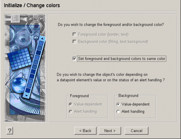
The Initialization window opens. Select the Change color option.
-
In the Initialize/Change colors panel select the check box Set foreground and background colors to same color.
-
At the bottom of this dialog you specify that the color changes are based on a change of value (see figure below).
-
Click on Next > to access the next panel (see below).
-
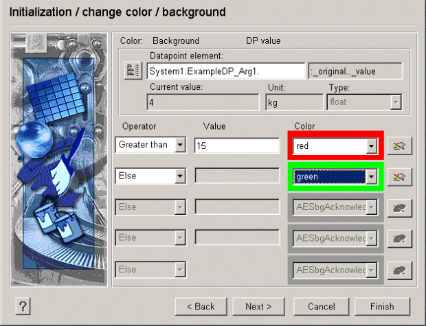
Select the data point whose value changes should trigger a color change.
-
For each color change, enter the operator (for example, smaller, greater or equal) and an appropriate threshold. You can define a maximum of 5 color changes per DPE.
-
Click on the buttons to the right of the color fields to open the Color Editor and select the corresponding color.
Many colors have already been defined in WinCC OA and can be selected using color names.
-
Click on the Finish button.
You can define up to four thresholds that should trigger a color change in a panel.
If you want to distinguish more conditions, change to complex configuration and customize this script.
Color for data type bool
If you have selected a data point with a Boolean data type, there are only two values available. You can define two different colors, for example to display whether a valve is open or closed.
For alert handling, define what value represents the good range and what alert color and alert class should be used. You can specify this also in the PARA module using the config _alert_hdl panel (See Module PARA, Config Alert handling).
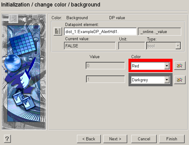
Example
Interpretation of the above figure with Boolean data type:
-
Data point ExampleDP_AlertHdl1.:_online.._value equals (FALSE = fault = alert color red).
-
Data point ExampleDP_AlertHdl1.:_online.._value equals (TRUE = good range = object color).


