Panel topology/Group alert example
This topic is intended as a guide, and summarizes the steps involved in creating a project using WinCC OA and the panel topology/group alert facility. The process displays shown have only been provided for illustrative purposes and have no other significance.
The following example is based on the assumption that you have created a new project. There is no reason why you should not open an existing project, however, and use its panels when creating the panel topology.
![]() Example
Example
Create a panel topology using new panels to look as shown below.
When configuring this panel topology you also need to create the new panels that belong to it, which will subsequently be edited using the graphics editor (GEDI). Finally you will generate the group alerts for all the panels in the topology.
Objective:
Using the STD_symbols you will be able to trigger an alarm in one panel that will be displayed in the base panel by means of the group-alert reporting feature. You will be able to perform individual operating actions in the base panel. Cross-selection of panels from amongst the process displays shall be implemented using simple STD_symbols (without objects for graphical reporting of alerts) taken from the symbol catalog.
Solution:
-
Start WinCC OA.
-
Open the Topology configuration panel from the System Management panel by clicking on the "Panel topology" button in the "Settings" tab.
-
Select a panel template and screen resolution that looks best for your topology. (see also Selecting a panel template)
-
Create the tree structure (topology) shown in the screenshot above. To do this use the buttons in the "Node" section on the right of the Topology configuration panel. (see also Configuration panel for the Panel topology/Group alert facility - Node)
Details of the buttons and functions in this panel are given in the section Setting
the node parameters. When you set the node parameters you must also define a
new panel, which is then linked to this node. In addition you can select an icon (from
the "/pictures" folder of the project or WinCC OA directory) to
be displayed on a direct-selection button if you configure this panel to such a button.
(see also Configuration of the direct-selection feature)
Use the
![]() "New"
"New"
button to create the panel in the directory <proj_path>/panels (or
in a sub-directory- see also Creating a new panel).
Leave the rest of the settings in this panel with their default values. In theory you only need to define the panel and node name that you want to use in the panel topology.
-
After configuring the tree structure, save the panel hierarchy and generate the group alerts. Close the Topology configuration panel.
-
Now use the GEDI graphics editor to edit the "empty" panels you have just created. In this example we only need to edit the panels
Plant_3andPump P0815in order to illustrate the panel topology/group alert facility. You can however use the symbol catalog in GEDI to construct your panel to your own design (see also STD_symbols, basics). The panel might for instance look like this:
The following STD_symbols have been used in this panel: STD_PANELS - PT_sum3, PT_jump,
STD_PICTOGRAM - ICON_COMPUTER, ICON_PLC. Clicking on the "Pump P0815" (PT_sum3)
button should open the child panel Detail_3.pnl defined in the
panel topology, where the pump P0815 is represented schematically. The button on the
right (PT_jump) is provided for panel cross-selection, i.e. clicking on the button opens
the panel Plant_1. This button does not report any group alerts
should any arise in the linked panel. The child panel Pump P0815
should contain symbols allowing additional operating actions to be performed on the
pump. The panel might accordingly look like this:
The symbols used in this panel are pump (PUMP) and LED (Led_1). The LED is included to display the pump status (on or off). The LED is referenced to the data point element ".state.on" of the data point P0815 (data point type PUMP2), which is generated automatically when you insert the pump in the panel. A text box has also been integrated displaying the actual speed.
-
You can add symbols to the other panels in the same way.
-
Leave the settings in the Prio.ranges at their default values. (see also Configuration of priority ranges).
-
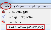
Click on the option Tools -> Start RunTime (<project_name>) in the GEDI menu.
-
A Login panel opens prompting for user details. After logging into the WinCC OA system, the base panel is opened automatically displaying the start panel defined in the panel topology.
-
Configure the direct-selection buttons in the navigation bar to the panels
Plant_1.pnltoPlant_3.pnl(see also Configuration of the direct-selection feature). -
Switch to the process display
Pump P0815and trigger an alert using the simulation panel of the pump P0815 (e.g. dry run). The alert is immediately reported to the central main panel and displayed in the symbol below the relevant direct-selection button (see screenshot below). In addition an alert is reported through all the panels defined in the topology and displayed below the "Start" button.
Additional operating actions
You can now perform further operating actions in the base panel:
-
Open the process displays using the direct-selection buttons or from the Start cascade
-
Open the independent panels (System Management, Variable Trend, Alert Panel, Online Help, ...)
-
Acknowledge the alerts in the alert bar (left-click on the three red exclamation marks). The user must possess suitable permissions in order to acknowledge alerts (see also Authorization levels).
-
Trigger additional alerts (depending on the parameters set for each of the standard symbols)
-
Change the current user (right-click on the field displaying the user name beside the System Information and select the option "Login as..." in the context menu).
All panels that are part of the project are now saved in a hierarchy. Panels can be added to this hierarchy or removed as required.


