Display of an Alert for an Object
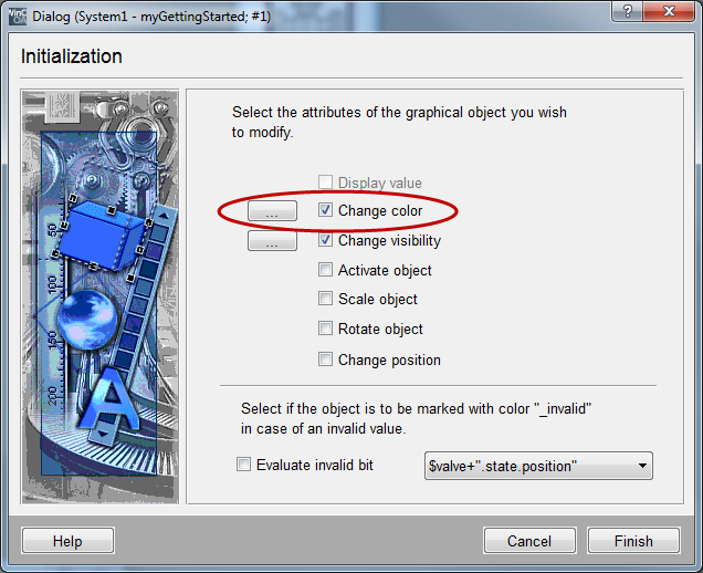
Alertsin the process image can be displayed in different ways. The background or foreground color of the device symbol can be used directly. Thereby, the alert state color will be shown in case of a state that has to be acknowledged or displayed. Otherwise, the original color will be shown, meaning the color that was used when the object was created. You can configure this using the wizards as shown in the figure on the page Dynamization of Graphich Elements.
The text fields that are used for the display of levels in the tanks T1 and T2 will be also used for the alert display.
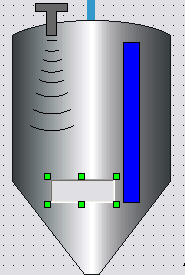
Select the value display and create a color change of the background color depending on the alert handling using the wizard (initialize). Enter T1.level or T2.level for the data point element.
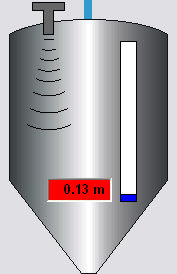
You can already test the alert display in the value display. Open the process image in the preview of the GEDI and set the value for the level in the tank to a value of 0.10 m. A low alert will be triggered immediately and will be displayed through fast, red blinking of the background in the text field.
Acknowledgement Event
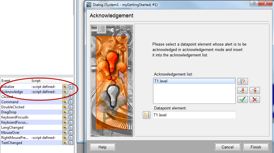
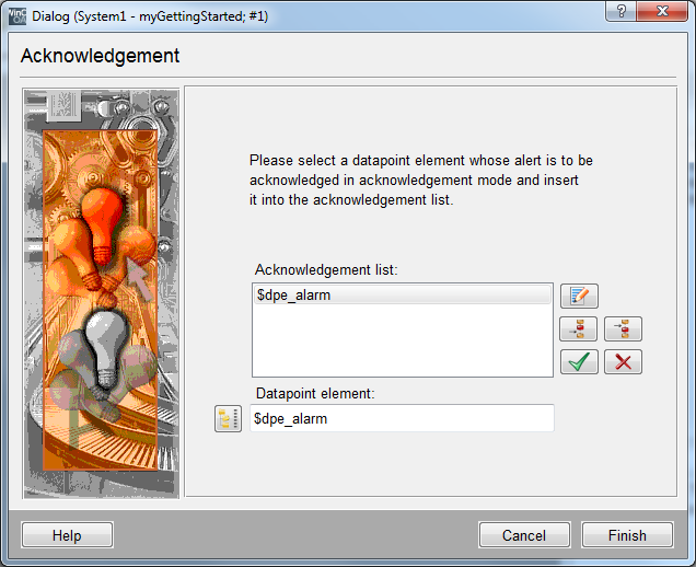
In order to acknowledge such an alert display directly in the process image or that you can use the acknowledge all option in such a panel, you have to process the acknowledgement event. You can configure this using the wizard.
-
Select the text field for the level display of tank T1.
-
Click on the symbol Open attribute wizard next to Acknowledge in the property sheet.
-
Enter T1.level in the data point element field, and apply the value by clicking the button "Add"
 in the acknowledgement list. Since no other alerts of other
data point elements should be acknowledged, you can finish the
configuration.
in the acknowledgement list. Since no other alerts of other
data point elements should be acknowledged, you can finish the
configuration. -
Configure T2 in the same way as T1.
If this object range (for example the background color) is used for the display of the operating state in the earlier mentioned case of alert display, this can lead to unintentional overlapping of information.
Separate Alert Display
The display via an own graphic element in the device symbol,like we did for the alert display in the pump symbol, may help in this case. Complete this display also with an acknowledgement entry in EventAcknowledge for P1.alarm.

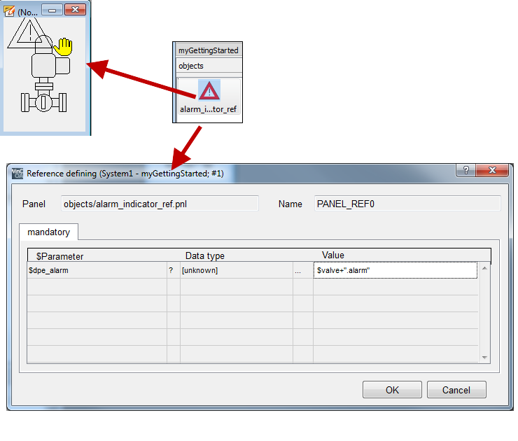
As for the pump, create an alarm display for the valves. Instead of integrating it in the valve reference object, create it as a new reference object. The advantage is that you can add it later to arbitrary device symbols.
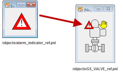
The following instruction helps you to create a reusable alarm display and to integrate this in the valve symbol.
-
Create a new panel with the size of 120x90 pixels and save it under
.../panels/objects/alarm_indicator_ref.pnlin your current project directory. -
Draw a polyline in the form of an isosceles triangle and select red for the background color and black for the foreground (border color). Note: For a grid setting 8x8 the horizontal base should be 8 grid spacings (64 pixels) and the vertical dimension 7 grid spacings (56 pixels).
-
Draw another polyline in the form of an isosceles triangle. For the background color, select white and for the foreground color red. Adapt the second triangle as shown, in the first triangle. Note: you can create the second triangle as a copy of the first - change the colors and size proportional.
-
Add two short, straight lines with the line width 2 in order to stylize an exclamation point. Draw very short lines using the zoom mode of the GEDI and with a minimized grid. Alternatively, you can draw longer lines and shorten them through the settings top and bottom in the property sheet.
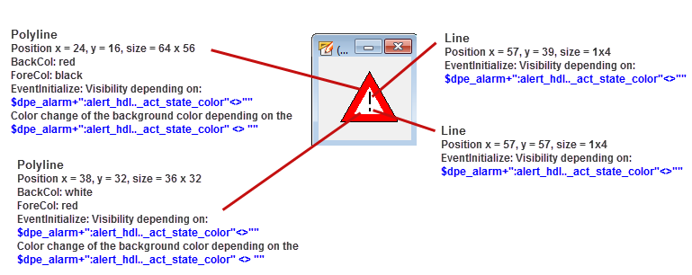
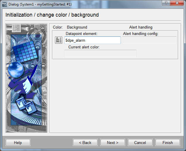
The next step is to define the dynamic properties of the alarm display. Use the simple configuration (wizard) again. However, there is one new characteristic: the data point definition does not containany static address parts. For the new $ parameter $dpe_alarm a complete data point element must be defined. The alarm state of this data point element will be displayed.
The second part $dpe_alarm is not an element of this data point but the definition of an attribute for a config (see chapter Addressing of Data Point Elements / Configs / Attributes). The value of the data point element will not be evaluated but the current state color of alarm handling for this element. Accordingly the configuration is different.
-
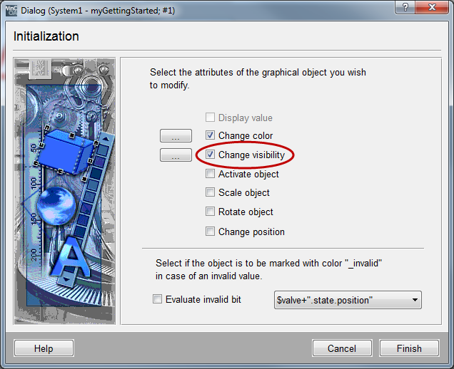
Select all 4 graphic objects the reference object is composed of together and open the simple configuration (wizard) in the property sheet, "standard" tab for initialize.
-
Select the animation type "Change visibility".
-
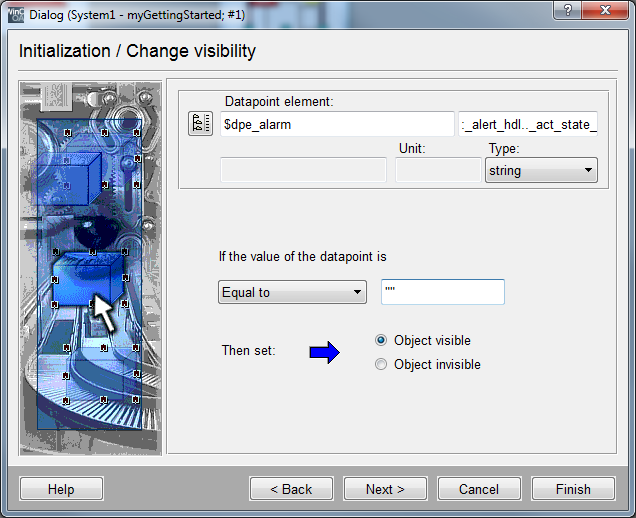
Enter the string $dpe_alarm in the data point element field.
-
Enter the string ":_alert_hdl.._act_state_color" in the field next to it.
-
Select the data typestringf rom the combo box type .
-
In the field next to the combo box (relational operator) "equals" enter two quotation marks "" (comparison with an empty string) - when the state does not need to be acknowledged or displayed, an empty string will be returned.
-
Select "Invisible object" for this state. The whole alert display will not be shown as long as everything is OK.
-
Complete the step by selecting Finish.
The display should not only be visible in case of an alert but also display the current color of the alert state. By directly applying this color, the display can adapt an arbitrary color defined in the specific alert class. You do not have to consider this in the configuration.
-
Cancel the multiple selection and select only the outer, red triangle of the alert display.
-
Open the wizard for simple configuration for the Initialize event.
-
Select the option "Change color" in addition to the existing configuration of the visibility.
-
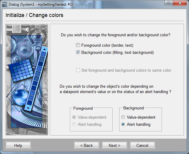
Next, select "Background color" and "Alert handling". Click on Next>.
-
Enter $dpe_alarm In the field data point element and close the configuration by clicking on Finish.
-
Open the wizards for Acknowledge and in the field data point element enter $dpe_alarm. Apply this value by clicking on
in the acknowledgement list. Close the
configuration by clicking on Finish. -
Save the reference.
The display can still be visible and blinking even when you have corrected the alarm triggering state. Also the state WENT/UNACKNOWLEDGED must be displayed for used alarm classes. In this case, acknowledge the alarm and the alarm display will not be displayed anymore.
Now add the new universal alarm display to the valve reference object. You can
find the display "alarm_indicator_ref" in the catalog (see first figure on the page
Use of ready
Symbols for Data Display) of the local project directory in the
graphic editor GEDI. If you like, you can also assign a catalog icon to this
reference - you can find an icon under
.../pictures/indicators/alarm_indicator.bmp.
-
Open the reference GS_VALVE_ref.pnl (valve reference) in the graphic editor.
-
Drag the reference object alarm_indicator_ref from the catalog into the valve reference panel.
-
Assign the string $valve+".alarm" to the $ parameter $dpe_alarm of the display in the automatically opened configuration dialog. This is necessary since the alarm display expects identifier strings and the parameter $valve of the calling reference only represents the data point name (= 1. level).
-
Minimize the alarm display a little bit and place it top left in the symbol display.
-
Save the valve reference panel.