STD OBJECTS
The former ActiveX symbols have been replaced by standard objects. The standard objects are installed by default. Not all former ActiveX STD objects are available as standard objects yet. You can find the available objects in the list below:
Please note that all still existing 32bit ActiveX objects only remain for compatibility reasons and must not be used anymore.
| Symbol | Symbol name | Description |
|
|
3StateSwitch | Switch for three different states |
|
|
4StateSwitch | Switch for four different states |
|
|
ChartPieVals | Value display as a pie chart (value in %) |
|
|
CircularAnalog | Analog circular display |
|
|
CircularAnalog_2 | Analog circular display |
|
|
CornerAnalog | Analog corner display |
|
|
KnobSelector | Circular adjuster |
|
|
NumericLED_10 | Numeric LED display for 10 digits (2 of which decimal places) |
|
|
NumericLED_4 | Numeric LED display for 4 digits (2 of which decimal places) |
|
|
NumericLED_6 | Numeric LED display for 6 digits (2 of which decimal places) |
Three example standard object reference panels are described below.
In all reference editors press OK to save and Cancel to discard changes.
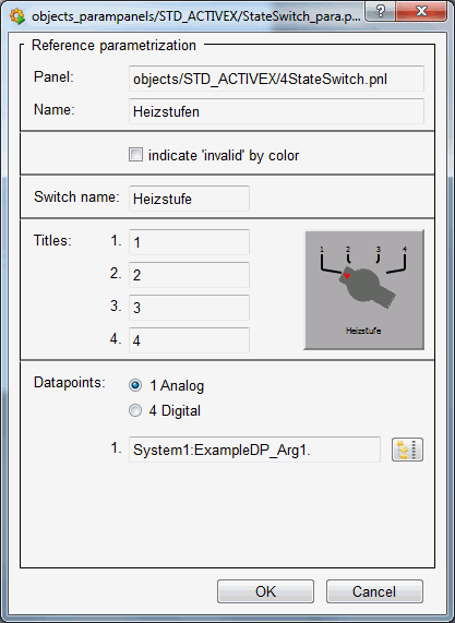
4StateSwitch
Displays four different states. When you drag the "4StateSwitch" out of the catalog and into the panel, the following reference editor is opened:

This panel displays the following:
Panel : Grayed-out text field indicating the path to the reference.
Name : Enter the specific object name used to address the object in scripts.
indicate "invalid" by color: When selected, this option displays a set invalid bit (invalid original value) by changing color (to light blue - invalid).
Switch name : Text to be displayed below the switch.
Titles 1, 2, 3, 4 : Enter text or numbers (e.g. Min, Max, 1,2, etc.).
Data points Analog/Digital : Four data point elements must be entered for digital values. You only need to enter one data point element for analog values.
The data points themselves must be selected using the data point selector button
![]() .
.
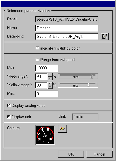
CircularAnalog
Typical circular display, e.g. revolution counter or speedometer.

This panel contains the following fields and buttons:
Panel : Displays the directory path to the reference.
Name : Enter the specific name of the object.
Data point : Use the DP selector to select the desired data point.
indicate "invalid" by color: When selected, displays a set invalid bit (invalid original value) by changing color (to light blue - invalid).
Range from data point : If you have created a range for the data point, if selected it is used as a
limit, otherwise the value for Min and Max.
Max: The upper limit to be used.
Red-range : Set the red range for the display either by using the spin buttons or the slider.
Yellow-range : Set the yellow range for the display either by using the spin buttons or the slider.
Min: The lower limit to be used.
Display analog value: If selected, the current value is displayed below the pointer display.
Display unit: Indicates the unit for the data point element (see Config _common).
Colors: Button opens an editor for customizing pointer color, background color and text color.
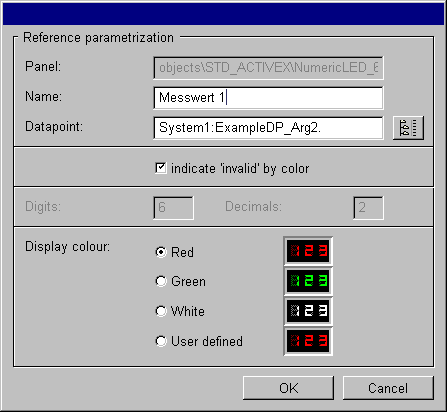
Numeric_LED
Digital display of a reading.

This panel contains the following fields and buttons:
Panel : Displays the directory path to the reference.
Name: Enter the specific name of the object.
Data point: Use the DP selector to select the desired data point.
indicate"invalid"by color: When selected, displays a set invalid bit (invalid original value) by changing color (to light blue - invalid).
Digits: Indicates the maximum permissible number of places before the decimal point for the DPE original value.
Decimals: Indicates the number of places after the decimal point for the DPE original value. This decreases the number of places allowed before the decimal point.
Displaycolor: Select red, green or white from the radio box or select User defined to open a color customization dialog box.


