Connectors
Connectors are used to connect two connector points with each other via a polygon or a pipe. Connector points are set in the reference panel the GEDI, in accordance to the complex objects in the panel. They are defined per panel, not per shape, as they are only relevant for complex objects (e.g. a motor, valve, switch, etc.) and not for primitive shapes.
The auto-routing calculates all vertices of the connector object, therefore the whole geometry of the connector changes on recalculation. As a consequence, the connector object can not be modified like a normal polygon, e.g. it can not be moved, scaled or rotated. However, it is possible to change the vertices manually. For this it needs to be kept in mind that changes will be lost when a recalculation happens (e.g. one connected reference is moved).
There are 3 different kinds of connectors: polygon steps, polygon curved and pipe. The difference between step and curved polygons is the way vertices will be drawn. Curved polygons will use bezier curves when changing direction.
Connector Points
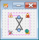
Connector points are the endpoints for the connector shape. They are created by right-clicking anywhere on the reference panel and selecting "Add connector Point" in the context menu. When adding a connector point, the panel will switch to showing the connector- and panel reference point for this panel only. A connector point is addressed by its name (also called id), which can be assigned via the context menu.
Connector points can be shown/hidden for all open panels via the "Show Panel Reference Point" toggle action in the View menu.
Connector Point Options
When right-clicking on a connector point, the context menu allows you to rename, remove, or change the orientation of the connector point. Holding the left mouse button and moving it will move the connector point.
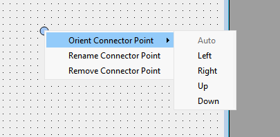
- Auto (default) - The connector point's orientation is not fixed. Pipe or polygone routes are calculated automatically, resulting in the shortest possible path being chosen.
- Left, Right, Up or Down - The connector point orientation is fixed. Pipe or polygon routes will always respect this connector orientation and the paths are defined accordingly.
Connector Types
You can choose from one of 3 connector types in the GEDI graphics objects menu bar:

|
Polygon as Connector (Steps) |

|
Polygon as Connector (Curved) |

|
Pipe as Connector |
They create either a polygon or pipe shape with their usual possibilities, which differs from the normal application by being marked as being a connector. In this case some specific rules apply, e.g. connectors can not be moved, scaled, rotated.
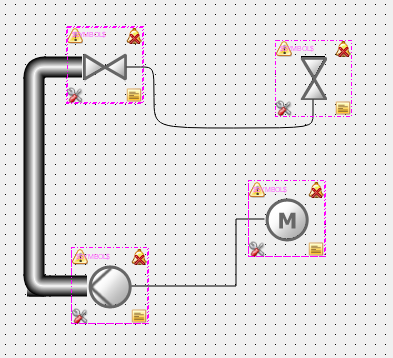
To construct a connector shape, select one of the above action, then move the mouse close to an available object (panel reference which has connector points defined) which will show its connector points. Press and hold the left mouse button when over an connector point, move the mouse to another connector point and release the button. While constructing a connector, the connector points will also be used as snap points.
When a panel reference with connector points is selected and mirrored, the connector points will still be their original position. This is due to the fact that mirroring a panel reference will in fact overparametrize each shape, which does not influence the connector points of the Reference itself.
Connector Functions
As connector shapes are specific cases of the polygon and pipe objects, their functions are grouped with the object documentation. All functions specific to the connector functionality are listed below.


