Freehand line and polygon
![]() To draw lines freehand
To draw lines freehand
- Click on the Polygon tool
 .
. - Click in the panel work area, hold the left button of the pointing device down and draw a curve by dragging the pointing device with a curving motion.
- Double-click the left mouse button to create the polygon.
![]() To draw a polygon
To draw a polygon
- Click on the Polygon tool .
- Left-click in the panel work area.
- With released mouse button move the cursor to the next point.
- Mark the corner points of the polygon by clicking in the panel work area.
- Double-click the left mouse button to create the polygon.
A double-click on the polygon in the panel during engineering opens the Clicked script.
The following functions are available in the property sheet: Line style, line width and surface formatting such as color and hatching.
The property Dash color can be used to display a two-colored line. With the default color "transparent" you get a single-colored line.
You can combine the freehand and polygon functions (click for each point in succession (polygon) and then press the left button of the pointing device, move the cursor to the next position and release it (freehand)).
If you hold down the Shift key during the process, you can draw lines or polygons in a vertical, horizontal, or angled orientation with 15 degree steps more easily.
Freehand lines and polygons in edit mode
The usual edit mode is indicated by nine editing points for an object. These can be used for stretching a line, moving or editing it.
Enable the " Edit Mode " in the Layout menu edit the shape of the selected object. The edit mode shows its corner points of the object. Thee can be moved, re-shaped to bezier curves, deleted or new corner points can be added.
- To move a corner point, click on it and drag it to the desired place.
- To add a new corner point, click on the line of he polygon.
In order to delete corner points, press the CTRL-key and click on them ([leftMouseClick]).
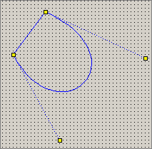
- To create a bezier curve, the polygon needs at least 4 corner points. Press CTRL+Shift and click on the chronological first corner point. The first/last created corner point is the start/end point of the bezier area. The 2 points between them are the control points. With a click on one of them the shape of the bezier curve area can be adjusted.
The edit mode is disabled by activating the "Move/Scale Mode" (see also Drawing and editing contours).


