Ethernet/IP Driver Configuration
Open the configuration panel of the Ethernet/IP driver via the System Management panel
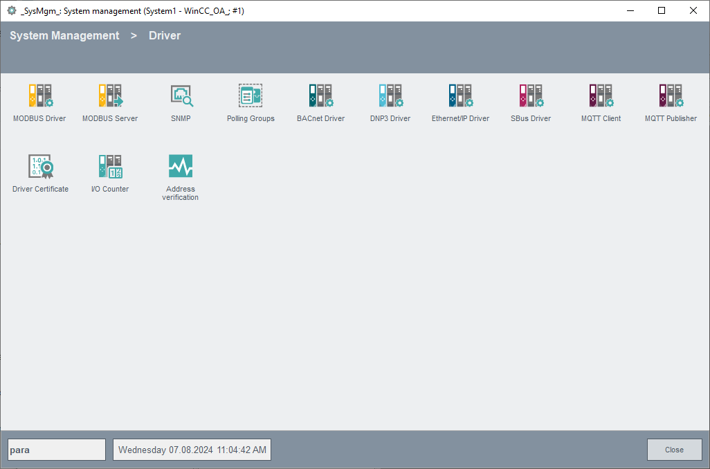
Click on the Ethernet/IP Driver button. Configure the PLC in the following parameterization panel. An internal datapoint of type _EIPConn is created for each PLC (see also Internal data points of the Ethernet/IP driver.)
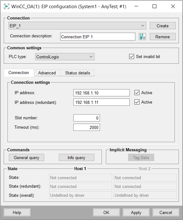
Applying changes to the parameters for an active PLC will cause the connection to close, the current request queue for that PLC to be purged, then the connection will be opened with the new settings.
Connection
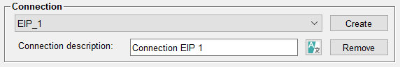
Create
Creates a new PLC data point with a specified name, and default values, after which it can then be parameterized. The parameterization will be applied only when the Apply button has been clicked. For changing the parameterization of a PLC datapoint choose it from the combo box, change the parameterization and click on the Apply button to save the new parameterization.
Remove
Deletes the chosen datapoint after confirmation of the security query dialog.
Connection description
Allows the user to enter any descriptive text to be associated with this PLC
Common settings
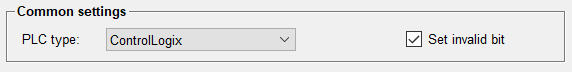
Following settings can be applied for the Ethernet/IP driver device:
PLC Type
Select the type of PLC. Available choices are:
- ControlLogix
- CompactLogix
- FlexLogix
- MicroLogix
- SLC5
- PLC5
- Omron CJ2
Set Invalid Bit
If this check box is ticked, the invalid bit is set for all input addresses of a corresponding PLC when the connection has been lost (“Not Connected” status).
Connection settings
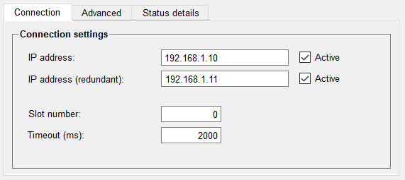
IP address
Defines the IP address of the first Network Interface Card (NIC). (The destination port number is always 44818 and cannot be changed.)
IP address (redundant)
Applies only to redundant connections. Defines the IP address of the second Network Interface Card.
Slot number
Applies only to ControlLogix. Enter the slot number of the PLC on the backplane.
For other PLC types, including PLCs with direct Ethernet connections, set this to 0.
Timeout (ms)
This sets the amount of time in milliseconds for a connection to be completed, as well as for a request to be acknowledged. (Since the underlying network layers do their own retries, there is no retry setting here. If the response to a request is not received within the timeout interval, a failure is declared, the connection is closed and the request queue is purged.)
Active
Tick this check box in order to activate the connection to the PLC. You can deactivate a device that is already created and configured. The status display changes from "Connected" to "Not Active" if a device is deactivated. If a connection has been deactivated, the driver does not communicate with the corresponding PLC anymore. So it is possible to prevent for example error messages when a PLC is intentionally removed from the system. Upon activation, a keep-alive query is sent to ascertain the availability of the PLC.
Advanced settings
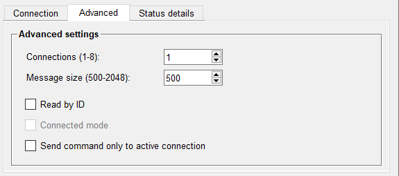
For Logix-family PLCs and Omron PLCs, the following additional performance settings are also available:
Connections (1-8)
This setting allows to establish up to 8 parallel connections to the PLC. Each connection uses an additional socket. Using multiple socket connections can increase the read throughput, however there is no significant performance gain using more than 3 or 4 socket connections. There are 512 server sockets available per driver instance. Increasing the number of connections will reduce the maximum number of PLCs per driver instance. E.g. using 3 connections per PLC would allow 170 PLCs per driver instance.
Message size (500-2048)
Allows to define how much data is transferred per message. This can increase the read-throughput, especially for array transfers and initial symbol retrievals. However, this option is only available when using newer PLC Ethernet adapters such as the 1756-EN2T. For adapters not supporting this option, an error message is sent to the log.
Read by ID
When using ControlLogix processors with firmware version 20 or higher, this setting allows polling by symbol-ID rather than by name. In case of long names, this could increase throughput by transferring more tags per message. This is not used for multi-dimension arrays, structure-members, program-tags, or cases where the ID is longer than the name.
Connected mode
Applies only to MicroLogix PLCs which commonly use non-connected mode. Some models require connected mode. In this case please activate this check box.
Send command only to active connection
Applies only to redundant connections. The default behavior is that commands are sent to both connections. If this check box is activated, commands are only sent to the active connection.
State Details
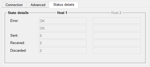
The State contains the following elements:
Error
Line 1 has the text of the latest basic error state for this PLC. See basic error state for a list of possible basic error codes.
Line 2 has more detailed information about the latest Ethernet/IP status, for example “Malformed tag name or tag does not exist”. See extended error status for a list of possible extended error codes.
Sent
Number of requests sent to the PLC.
Received
Number of requests accepted by the PLC.
Discarded
Number of requests (including connection attempts) which did not succeed.
Commands
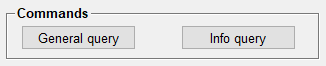
Following commands are available for the EIP driver
General Query
Clicking on this button triggers a general query to the PLC. All data that is parameterized for polling is queried immediately and the GQ bit of the DPE is set. All data that is parameterized for single-query is automatically grouped into blocks and queried, and the GQ bit is set accordingly. ( An automatic general query can be issued on connect if the “autoGQ” setting is made in the config file.)
If your project is configured as a redundant project, data from a general query with same values is only let through by the event manager when the config entry "redOldNewComp" in the event section of the "config.redu"-file is set to 0.
Info Query
For Logix-family PLCs and Omron PLCs, this button allows to manually trigger a new tag-info query to the PLC, which retrieves the PLC’s basic symbol table. The queried info includes the symbol IDs as well as data-types and array sizes used for address validation. The driver uses this information for validating tags and array length.
When Read by ID is checked or when using an Omron PLC, the symbol table is also queried automatically at first establishment of the connection.
Implicit Messaging
The following section is only available for ControlLogix and Omron PLCs.
Tag Sets
Clicking this button opens the panel to configure Tag Sets for the selected PLC. For more information see EIP Tag Set Configuration.
State
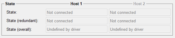
The State consists of following elements:
State
State of the first connection. The following states are possible:
| Value | State |
| 0 | Not connected |
| 1 | Connected |
| 2 | General Query |
| 3 | Not Active |
| 4 | Pending |
| 5 | Internal state |
| 6 | Internal state |
| 7 | InfoQuery |
Redundant State
State of the redundant connection. The possible states are the same as for the first connection
Overall State
The overall state of the driver, according to the common connection state.


