Ethernet/IP Implicit Messaging
Implicit Messaging allows WinCC OA to connect to a PLC and request a scheduled stream of updates of a specified Tag Set. Once this request is accepted by the PLC, it begins sending UDP datagrams containing the data for the entire Tag Set, at the specified rate. The EIP driver does not need to poll for these, merely to send a periodic keep-alive message at a lower interval.
The amount of possible Tag Set connections is set by the device limit.
There are a few limitations to consider:
- WinCC OA is always the originator of the connection. It is not necessary nor supported to configure the PLC to attempt to establish a connection to the WinCC OA system. No EDS files are necessary on either side of the connection (only the built-in file for the PLC itself, in the PLC tools).
- By default, all implicit connections would be processed in one instance of the EIP
driver. This is because PLCs typically send implicit data to port 2222, and only one
process may listen to a given port. Since the CPU load for processing implicit
messages is much lower than for polled messages, this should not be a problem.
However, the port can be changed using the config entry
[eip]
                        implicitPort
, which allows an EIP driver instance to request that the PLC use an alternate port for implicit data sent to WinCC OA. Each driver instance must have a unique port. Implicit data sent to the PLC still uses port 2222 regardless of this setting. - Different PLC types have different limits to the number and size of Tag Sets. An Omron CJ2H allows up to 256 Tag Sets, of 1-8 tags each, and 1440 bytes. An Omron CJ2M PLC is limited to 1280 bytes. The same tag cannot be in multiple Tag Sets.
- While each Tag Set consumes a connection in the PLC, the same is not true on the WinCC OA side. The driver has a maximum of 512 sockets per instance. Of these a configurable number (1-8) are used per PLC for explicit messaging connections. One socket is used to listen for all incoming UDP data, one to send all outgoing UDP data, and one to listen for incoming UDP commands. A socket is used temporarily to establish each implicit connection, then freed.
- Connections are point-to-point, not Multi-Cast.
- Because UDP port 2222 is used for incoming data, this port must be open in the system firewall. If alternate ports are used, these must be open as well.
Implicit Messaging is only supported for ControlLogix and Omron PLCs.
Omron PLC Configuration
To configure a tag for implicit messaging, it must be added to the Symbols table in CX-Programmer and set as a Net. Variable for Output as shown in the figure below.
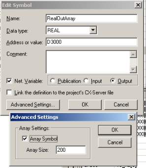
These should then be downloaded to the PLC.
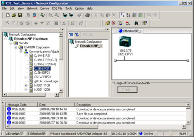
Next the Omron Network Configuration utility must be used to create a network configuration. Therefore, the used PLC must be added. It is not necessary to add a node for the WinCC OA server. Note that for a CJ2H PLC the built-in Ethernet adapter CJ2B-EIP21 should be used. Afterwards the IP address of the PLC must be defined.
Create "Out – Produce" Tag Sets containing up to 8 tags. And up to the above-mentioned total size. It is not necessary to configure "Connections" because these would be used for PLC-initiated connections, which are not supported. Likewise, "In-Consume" tags are not currently supported.
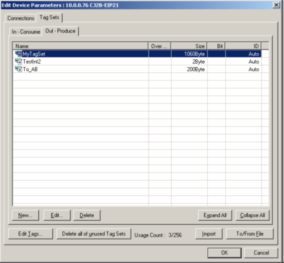
The "Import" button can then be used to pull in all Output tags from the current CX-Programmer project.
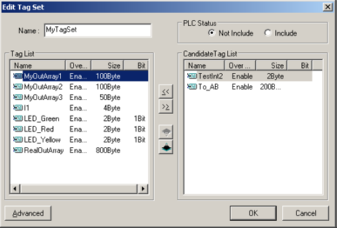
Make sure that PLC Status is set to "Not Include".
Once all tags of the Tag Set are defined, keep these tags and their byte-offset in mind for the configuration in WinCC OA afterwards. For example, MyOutArray1 is at offset 0, MyOutArray2 is at offset 101. These values must be used later to read the tag values from the Tag Set in WinCC OA.
Then exit this dialog by clicking OK. Afterwards another dialog appears, which shows the total size of the given Tag Set. Keep the total size in mind and click OK again.
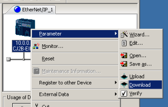
Finally, the project must be saved, and the parameter must be downloaded to the PLC by right-clicking on the PLC on the network layout, selecting "Parameter" and then "Download".
ControlLogix PLC Configuration
To use implicit messaging with a ControlLogix PLC Controller Tags must be created in Logix Studio. Therefore, right-click on Controller Tags, then select "New".
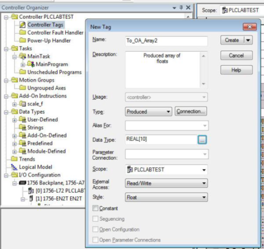
The tag can be a scalar, an array, or a user-defined type, but only one tag can be exchanged per implicit connection.
Define the tag name, the datatype and optional array dimensions and set the Type to "Produced" in the dialog shown above. It is not required to set up a connection.
Afterwards save the configuration and download it to the PLC. The configured tags can now be requested by WinCC OA using Implicit Messaging.
WinCC OA Address Configuration
To use an Implicit Tag Set in WinCC OA the following things must be configured:
- A PLC record - The PLC Connection must be configured in WinCC OA.
- A Tag Set record, named the same as in the PLC, for example MyTagSet. These are per-PLC and are case-sensitive. For more information please refer to WinCC OA Tag Set configuration.
- One or more datapoints with an active address config, pointing to this PLC with Receive Mode Implicit and specified Tag Set. Additionally, the byte-offset for the tag’s data inside the Tag Set must be defined.
For example, the following address configuration uses Implicit Messaging to receive a dyn_int datapoint with the transformation int16. This means that each array element is 2 bytes long. The address "MyTagSet/0:50" specifies the Tag Set "MyTagSet", an offset of 0 and 50 elements. The offset is mandatory, even if starting at zero, the length suffix is only used for arrays.
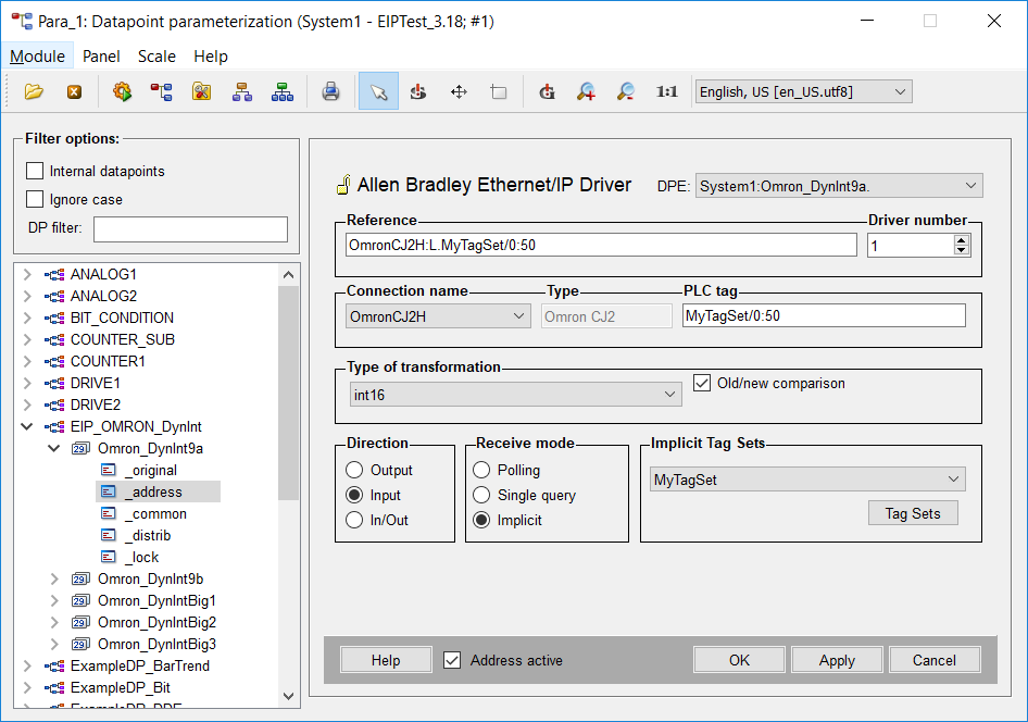
It is up to the user to configure the datapoint type, transformation type and offset to make sense of the incoming data. This allows flexibility in case the data should be mapped in different ways.
It is also possible to map multiple datapoints to the same or overlapping offsets.
WinCC OA Tag Set Configuration
The following panel allows creating Tag Sets for a given PLC in WinCC OA. The panel can be opened from the EIP address configuration panel or from System Management / Driver / EIP by pressing the Tag Sets button.
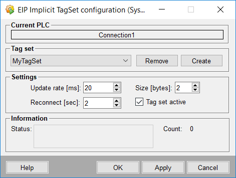
Initially, there are no Tag Sets configured. It is required to create one for each PLC Tag Set, which should be used to communicate with WinCC OA. The name and size of the WinCC OA Tag Set must match the PLC configuration exactly.
An Omron CJ2H allows up to 256 Tag Sets, although each uses a connection in the PLC. Tag Sets are defined per-PLC. The same name can be used for multiple PLCs, but a separate record has to be created for each PLC.
Create
Creates a new Tag Set data point with a specified name, and default values, after which it can be configured. The configuration will be applied only when the "Apply" button has been clicked. For changing the configuration of a Tag Set datapoint, choose it from the combo box, change the options and click on the "Apply" button to save the new values.
Remove
Deletes the chosen datapoint after confirmation of the security query dialog.
Settings
The Update rate defines how often the PLC streams the Tag Set in milliseconds. It is possible to go as low as 20ms, small values can however affect the performance of the WinCC OA Event Manager. Using arrays will present less load to the system than using individual values. For production the Old/New Comparison should be used to reduce system load.
The Reconnect text field specifies the number of seconds between attempts to re-establish the connection in case of a failure.
Size defines the size of the entire Tag Set in bytes. This value must be equal to the setting from the PLCs Tag Set.
Data-Packing for ControlLogix PLCs User Defined Types
When implicitly transferring a user-defined structure from a ControlLogix PLC, unfortunately the tools do not show the byte offsets for each structure member.
When changing data types from one field to the next, the ControlLogix PLC pads to the next 4-byte boundary. For example, a structured type with mixed data types might be laid out like this:
| Name | Type | Size | Offset |
| MyInt1 | INT | 2 | 0 |
| (reserved) | - | 2 | - |
| MyDint1 | DINT | 4 | 4 |
| MyReal1 | REAL | 4 | 8 |
| MySInt1 | SINT | 1 | 12 |
| (reserved) | - | 3 | - |
| UDT2.ComErr | INT | 2 | 16 |
| (reserved) | - | 2 | - |
| UDT2.Auto | BOOL | 1 | 20 |
| (reserved) | - | 3 | - |
| UDT2.OPLast | REAL | 4 | 24 |
| UDT2.OffAlm | BOOL | 1 | 28 |
| UDT2.OnAlm | BOOL | 1 | 29 |
| (reserved) | - | 2 | - |
| UDT2.PVLast | REAL | 4 | 32 |
| UDT2.PVRaw | REAL | 4 | 36 |
The total size of this example User Defined Type tag would be 40 bytes.
The total size can be seen in the tool by clicking on Data Types / User-Defined / used UDT. It will display the size in bytes for the whole structure.
Tag set active is used to activate or deactivate the Tag Set.
Information
The Status field shows the current status of the Tag Set. For failures, additional information is supplied to help isolate the problem.
Count shows the number of completed transactions for this Tag Set since it was activated, or the driver was started. This is updated every 5 seconds by default but can be changed using the config entry "StatCheckInterval".


