Setting the Simulation
How to integrate the simulation of device reactions in the example was already shown in the chapter Add the Simulation. Based on the steps described in that chapter, you should now also integrate a model simulation. Therefore, activate another script in the already started Control manager.
-
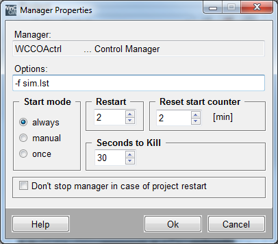
Switch to the console and open the manager parameter of the last opened Control manager. You can do this by double clicking on the appropriate row in the manager list or through the button "Change manager properties" [Ctrl] + [E] on the selected row.
-
The current properties should look as shown in the figure.
-
Change the manager properties in the field "Options:" from 'simDevices.ctl' to '-f sim.lst'.
-
Stop the manager and then restart it.
Each Control manager can process several scripts simultaneously. While only an
individual script (simDevices.ctl) was added in the chapter Add the
Simulation, now a list of scripts will be defined. Such scripts are
merely composed of an ASCII file. The file comprises a list of all scripts to be
started. The content of the file sim.lst in the directory
.../scripts/ looks as follows:
simDevices.ctl
simModel.ctl
The ending *.lst in '-f sim.lst' thereby shows that this is a whole script list and not an individual file. The start option -f (file) specifies this for the Control Manager.
In order to be able to change the simulation parameters through the interface, there is a properties panel for the scripts. This communicates through the data point SimControl of type GS_SIM with the current simulation program. This should be already a part of your application through Adding the Simulation.
As next step you integrate the delivered dialog for the simulation settings in the main image.
-
Open the main image
process.pnlin the graphic editor. -
Add a button and change the shown text to simulation.
-
Open the wizards for the simple configuration for clicked in the property window and "Standard" tab.
-
Select "Panel functions" and then "Open panel".
-
Select the panel
sim_settings_cp.pnlin the directory .../panels/details/ of the current project (the panel was added through add the simulation). -
Assign the panel name e.g. "Simulation".
-
Select the option "Child panel in the calling panel" and "centered" for the position.
-
Close the wizards through Finish.
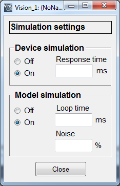
The ready result should look as follows at runtime. The response time for the device simulation serves for the virtual consideration of the communication runtime etc. The simplified physical model of the both tanks is calculated cyclical. With the "noise", the otherwise mathematically clean curves can be represented more realistic.
Additionally, you can switch the simulation of the application to manual mode through the mentioned data point also for all devices or you can create a defined initial situation for automatic mode. You should be able to activate these operating states through the process image using a button.
-
Add a button for the shut-off.
-
Configure the button for clicked. The data point element SimControl.devices.allOff should be set to "1" when clicking the button.
-
Add a button Auto mode.
-
The data point element SimControl.fullAuto should be set to 1 by clicking this button.
Both data point elements will reset by the simulation automatically after the processing. Open the application in the runtime mode and test the new functionalities.


