Definition of peripheral addresses for the S7Plus driver
This chapter describes the definition of peripheral addresses for the S7Plus driver.
Click on the _address config of a data point element, select the driver type SIMATIC S7Plus and click on Configure... to open the following panel.
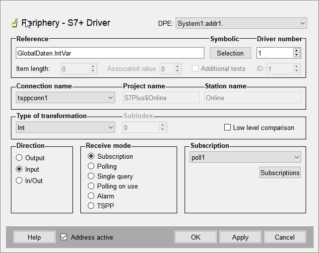
Reference
To define the peripheral address, type the respective address manually or click on the "..." button to browse the TIA project.
Syntax
Data Address:
<Symbolic Address in the PLC>[:length]Alarm Address:
<Symbolic Address in the PLC>:[associated value]:[additional text]Symbolic - Selection
Click on this button to browse the TIA project (if a TIA project is loaded and the driver is running) and select the appropriate symbolic address.
-
File browsing: Already configured addresses still work with the existing TIA export. A new TIA export is only necessary if the changes shall be applied to WinCC OA. In this case you have to reselect the TIA project (see also Engineering).
-
Online browsing: A reconnect is necessary to apply the changes to WinCC OA.
Existing addresses are not automatically invalid in case of changes to the TIA portal (e.g. adding new data blocks or variables).
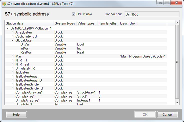
HMI visible
You can define which data shall be visible in HMI via the TIA portal. Per default this panel only shows data which is designated as "HMI visible" int the TIA project. Use this check box to define if data which is not "HMI visible" shall also be displayed in the browse result.
Station data
Shows all data of the station selected from the TIA project.
System types
Shows the type of the respective node, e.g. block, variable or tag.
Value types
Shows the value type of the respective elements
Item length
Shows the length of arrays and strings
Driver number
Must match the number of the S7Plus driver assigned to the connection.
Item length
This setting is optional and allows to define how many characters of a string or how many array elements shall be read.
Associated value
Defines if one of the associated alert values (programmed in TIA portal) shall be used as original value of the data point element. 0 means that no original value is set. Only available for alarming.
Additional texts
Defines if additional texts (info text + 8 additional texts) shall be sent as additional values for the WinCC OA alert. Only available for alarming.
Name
Connection name
Select the appropriate connection from the combo box.
Project name
Shows the name of the selected TIA project.
Station name
Shows the name of the station selected from the TIA project.
Transformation
Type of transformation
The transformation type is the interpretation of data which was read from the peripheral device. It must match the defined address type. The transformation type is automatically set when you select the symbolic address via the "..." button. Use the combo box to manually select the type.
There are the following S7 data types and WinCC OA transformation types:
| WinCC OA Transformation type | S7 value type | WinCC OA DPE type |
|---|---|---|
| Bool | BOOL | boolean |
| Byte | BYTE | uint |
| Word | WORD | uint |
| DWord | DWORD | bit32 |
| LWord | LWORD | bit64 |
| USint | UINT8 | uint |
| UInt | UINT16 | uint |
| UDInt | UINT32 | uint |
| ULInt | UINT64 | ulong |
| SInt | INT8 | int |
| Int | INT16 | int |
| DInt | INT32 | int |
| LInt | INT64 | long |
| Real | REAL32 | float |
| LReal | REAL64 | float |
| Date | UINT16 | time |
| DateTime | UINT64 | time |
| Time | INT32 | time |
| Time_Of_Day | UINT32 | time |
| LDateTime | UINT64 | time |
| LTime | INT64 | time |
| LTOD | UINT64 | time |
| DTL | 12 Byte Struct | time |
| S5Time | UINT16 | time |
| String | UINT8[] | string |
| WString | UINT16[] | string |
Low level comparison
This can only be used if the direction is set to input or in/out. If you select this option, the driver only sends data if the value has changed. The comparison is based on raw data without any conversion. The single bits of byte blocks are compared to old values. If a bit changes, the value in WinCC OA is updated.
Direction
Define whether values shall be sent (output) or received (input). If you select in/out, both (sending and receiving) is possible.
When the values of a data point element are sent in both directions (In/Out), then this data point element must not be directly subordinated to a struct node (structure of values).
Receive mode
You can select one of the following receive modes for the input:
- Subscriptions
- Polling
- Single query
- Polling on use
- Alarm (refer to S7Plus PLC Alarms for further information on receive mode "Alarm")
- TSPP (refer to TSPP for further information on receive mode "TSPP")
Subscriptions
This button allows you to create and configure Subscriptions. You can also select, edit, enable or disable already existing subscriptions.
Poll group
This button allows you to create and configure Poll groups. You can also select, edit, enable or disable already existing poll groups.
A poll group must not be used for polling and as subscription at the same time. For example, the poll group PG1 is used for an address with receive mode "Subscriptions", you must not use this poll group for an address with receive mode "Polling".
Address active
If you enable this check box, the address is created in the driver (see also reference tables). Attributes can be set and queried for an inactive address, however, the address does not exist for the driver. This means that no values can be sent or received from the PLC.


