Alert handling of continuous values
An alert handling of continuous values is used when the whole value range should be covered with specified intervals (limits). Depending on the defined alert classes for these ranges an alert is triggered as soon as the original value or online value takes on a value, which is in this alert range.
An continuous alert handling can be configured for the following data types: uint, int, float and bool.
Standard panel for alert handling of numeric values
The panel for alert handling of analog variables (int, uint, float) comprises two tabs.
Limits tab
-
Limiting Values: From the pulldown menu at the bottom ("2 ranges",... "5 ranges") select the number of alert ranges you want. You can select two to five ranges. Five ranges are required, for example, if you divide into a valid range with a warning and alarm range at both end limits of the valid range.
-
Limit operators : select from the combo box for every limit change, to which value the limiting value below shall be factored in. The limiting value can be either lower ("<"), then an alert handling for the upper limit will be already occurred when the value equals with the here entered limiting value (see example in figure above - a warning will be triggered as soon as the value 75 mor higher will be read). The limiting value can be entered also with the operator lower-equal ("<="). Then the alert for the higher limit will occur as soon as the entered limiting value will be exceeded (see example in figure above - an alert will be triggered as soon as the value 90 will be exceeded).
The top limit of the first range and bottom limit of the bottom range are defined by the limits of the WinCC OA value range of the related variable. Thus, the user does not specify these, they are automatically set.
-
Alert classes : select one of the 7 default alert classes (see also chapter _alert_class) or add a user-defined alert class using the DP selector on the right. The alert classes have to be assigned according to increasing priority. For the good range a alert class must not be defined.
-
Range texts: enter a text for each alert range; this text is displayed on the alert panel, e.g.: measuring sonde 2: CO content critical.
-
Hysteresis- if the checkbox is ticked, the entry of an upper and bottom limit is possible for every limit. The hysteresis values are entered relative to the limiting value. For more information about hysteresis you can find at the end of this chapter.
Parameters tab
The layout of the Parameters tab is similar to the Parameters tab of a sum alert handling.
Extended alert handling of continuous values
The extended configuration of the alert handling of continuous values allows setting the arithmetic operators of a limiting value, so that this results in overlapping thresholds. In this case, the limiting values are not defined between two thresholds, but for the certain threshold, whose value must match to trigger this alert.
This means that a specific alert is pending as long as a certain state, which replaces the alert handling or lets the alert handling go (WENT alert), has not occurred.
It should be noted that the limiting values must be entered in ascending order, i.e. in the highest range the highest value and in the first range the smallest value.
By default the extended alert handling is not available. This can be enabled by setting the config entry useExtendedAlarmHandling = 1 in the [ui] section of the config file. After a successful activation, an additional type is available in the combo box for setting the alert handling type - extended. Select this alert handling type for an extended configuration.
The alert_hdl.._act_state_text is not set correctly for extended alert handlings. Thus, it should not be used/queried. The alarm text and the color are not displayed in the panel.
If the config entry useExtendedAlarmHandling is set to FALSE (0), the "extended" alert handling type is not available in the combo box and thus an extended configuration is not possible anymore. Extended configurations that have been created beforehand will remain.
 Example
The figure above shows an extended alert handling with 4 ranges
Value <= 100 : Danger
Value >= 75 : Warning "High"
Value < 40 Warning "Low"
The following alert handles will be triggered when a specific value change occurs:
Continuous alert handling of boolean values
The alert handling of boolean values characterizes that an alert will be triggered only then, if one state occurs (TRUE or FALSE). Thus there are no limits or hysteresis definable.
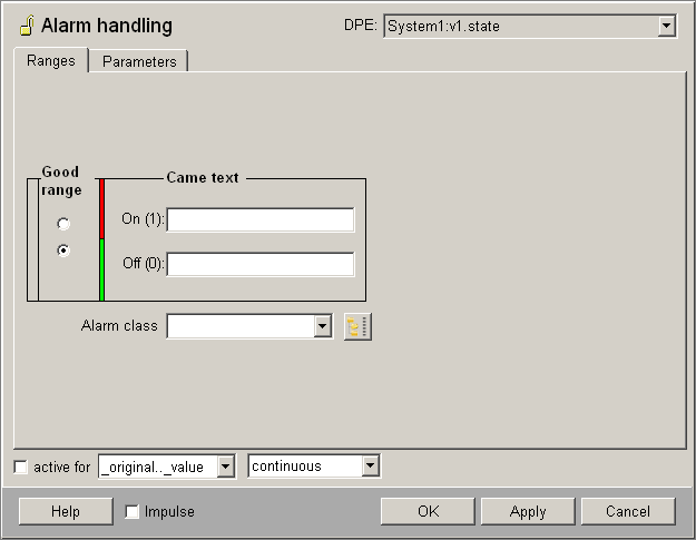
Ranges tab
-
Good range: by ticking the radio boxes can be defined, which state (On/Off) of the data point element is the good range. The color bar right to the radio boxes changes according to the selection.
-
Color bar: the red area is the alarm area, green is the valid range (normal range) in which the system runs properly, i.e. when no alert is to be triggered.
-
"Came text": enter for the both states ( one (TRUE) or zero (FALSE)) a text. The text of the alarm state will be shown in the alert panel, if the state changes. The Came text in the good range will not be shown in the alert panel, but can be also defined for requests (e.g. for the usage in the enum context).
-
Alert class: define for the alert state (not good range) one of the seven predefined alert classes (see chapter _alert_class (Alert class)) or apply a separate alert class using the DP selector on the right.
Parameters tab
The Parameters tab equals the parameters tab in the sum alert handling and is also there described.
Hysteresis
Fluctuation of a value between two ranges would trigger a number of alerts. This can be prevented by using lower and upper barriers (hysteresis), if desired.
The following applies depending on the value change:
-
increasing values: the lower barrier is added to the previous range. Only when this limit is exceeded the next range starts, e.g. range 3 is only reached after the lower barrier of range 3 is exceeded (see the figure above).
-
decreasing values: the upper barrier is added to the previous range. Only when the value drops below this limit the next range starts, e.g. range 2 is only reached after the value drops below the upper barrier of range 2 (see the figure above).
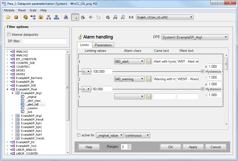
The lower and the upper barrier must be entered relative to the limiting value in the alert handling panel. This means that the entered value for the hysteresis will be added to the limiting value or subtracted from the limiting value depending on the barrier. See figure below.
The image below shows an alert handling with hysteresis for two ranges 60_alert and 040_warning. This image shows an alert handling with temperature values. If the temperature raises to 50 +1 degrees, a warning is triggered. If the temperature raises to 100 +1, an alert is triggered. If the temperature falls, the value of the hysteresis is subtracted, meaning 100 -1 (see figure below).
The maximal value for a hysteresis of type ulong is 2147483647.
If you change the limit value, reconfigure the hysteresis.


