IEC 61850 client address panel
For defining a peripheral address you have to right click on a data point element and select "Insert config". Insert a new "Periphery address" config and select the " IEC 61850/61400 CLIENT" driver type from the combo box. Clicking on the Configure button opens the configuration panel for the peripheral address of the IEC 61850 client.
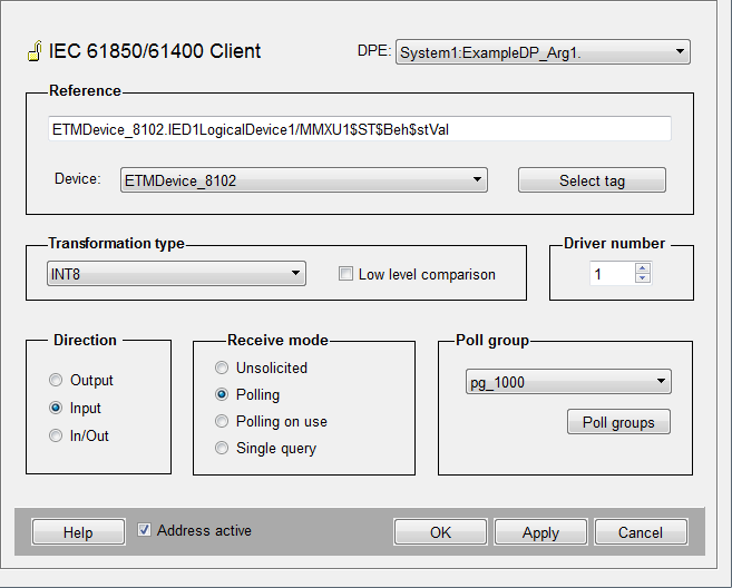
Reference
The reference string applies to a tag address (data attribute) of the device and is displayed in MMS format. It must be constructed as:
<WinCC_OA_project_device>.<LogicalDeviceName>/<LogicalNode>$ FC >$ DO >$ DA >.
A tag address can be entered manually or by using the Add reference button.
In case device redundancy is configured, the name of the primary IED (which is part of LogicalDeviceName) is automatically replaced with the IED name of the secondary IED, when the secondary IED shall be addressed.
Device
Displays the name of the selected device. To change the device select an available device from the drop down list.
You need to select the driver instance number manually by using the spin button of the frame Driver number.
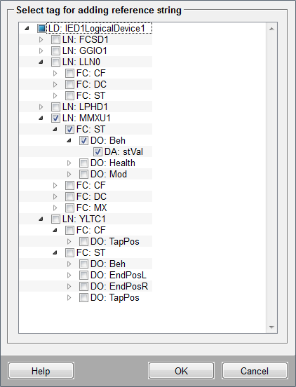
Add reference
The Add reference button opens a panel displaying the device structure. Select a data attribute and click OK, the reference string of the selected tag address will automatically be entered into the reference text field, an appropriate transformation type will also be selected automatically.
The data type of the selected tag must match the data type of the data point element or an appropriate mapping must be available.
Transformation type
The transformation type is an interpretation of the data read from the peripheral device. On using Add reference the correct transformation type is determined automatically. If a reference is added manually, the correct transformation type must also be selected manually.
| IEC 61850 type | WinCC OA transformation type |
|---|---|
| BOOLEAN | BOOLEAN |
| INT8 | INT8 |
| INT16 | INT16 |
| INT32 | INT32 |
| INT8U | INT8U |
| INT32U | INT32U |
| FLOAT32 | FLOAT32 |
| FLOAT64 | FLOAT64 |
| ENUMERATED | INT32 |
| CODED ENUM | BITSTRING |
| OCTET STRING64 | OCTET STRING64 |
| VISIBLE STRING64 | VISIBLE STRING64 |
| VISIBLE STRING255 | VISIBLE STRING255 |
Transformation types can usually be mapped to more than one type of data point element. E.g. BITSTRING can be mapped to data point elements of type int, uint and bit32.
Low level comparison
Low level comparison can be activated only when the direction is set to "Input" or "In/Out". Input data is updated only when the value changes. The low level comparison compares its existing value with a new value which is received from the device.
Driver number
Manager number of the started IEC 61850 client (e.g. -num 1).
Direction
Defines whether the value of a data point element is sent to the device (Output), the value is received from the device (Input) or the value is sent/received bidirectionally (In/Out).
Receive mode
There are four different receive modes for the input and in/out direction:
Unsolicited
Use unsolicited if data transmission shall be initiated by the IED . The following requirements apply:
-
The tag address selected must be a member of a dataset.
-
The dataset must be assigned to a report control block.
-
The report control block must be enabled.
The data will be retrieved according to the trigger options configured for the applying report control block.
Polling
Polling is used to collect the value of a data attribute at an interval configured in WinCC OA. The interval shall be defined in the poll group.
Polling on use
Polling on use is used to collect the value of a data attribute at a configured interval only if the data point element is selected either by the UI or through control function methods. The interval shall be defined in the poll group.
Single query
If the receive mode is set to "Single query", a query is only possible when it is triggered via the internal data point "_DriverCommon.SQ" by selecting the associated data point element. Data will then be retrieved and the corresponding data point element will be updated.
-
Polling is defined for a data point element and the respective poll group is inactive. If the tag address defined at the data point element is also part of a dataset assigned to an active RCB, the data point element will also receive data even though the poll group is not active.
-
Unsolicited communication is defined for a data point element and the respective RCB is inactive. However, if polling is configured and active for another data point element with the same tag address, the first data point element will also receive values despite the inactive RCB.
A data point element receives values when the driver receives data for the respective tag address. However, there is no distinction between polling and unsolicited data transmission at this point. This leads to the following behavior:
If the data point element shall not receive data, the respective address must be deactivated.
Poll group
Poll groups need be configured for polling and polling on use. Either select an already existing poll group or create a new one by clicking on the Poll groups button and entering the required information.
Address active
If the Address active option is checked, the IEC 61850 client uses the reference address to send or receive values. In case the Address active option is unchecked the address exists but is disabled, which means that no values can be sent or received.


