Panel Topology
The panel topology in WinCC OA is a tool for the easy realization of user interfaces. The main focus of this function is to provide navigation elements for the selection of process images and automatic display of sum alarms. The basis is the logical, functional and geographic hierarchy of the plant as well as the hierarchical structure of process images (panels).
For this purpose, the panel topology provides the following basic elements:
- Templates for the design of the user interface
- Tool for thegeneration of plant hierarchyregarding the process images in a tree view including automaticpanel sum alerts.
- Numerous navigation elements
- Numerous display elements for the sum alerts>
In order to show the advantages of the panel topology in practice, you will now integrate the already created plant images (tank system and trends) in the panel topology.
- Open the configuration dialog of the panel topology via the
 button of the tool bar
of the graphic editor. Alternatively, you can open the panel topology via the System
management panel > Settings tab > Panel topology.
button of the tool bar
of the graphic editor. Alternatively, you can open the panel topology via the System
management panel > Settings tab > Panel topology. - In the now displayed topology tree, there are two visible main nodes - the "StartPanel" and "...". You can add the hierarchy of your plant under the StartPanel. The second node provides access to the system functions (System Management).
- Right-click the node "StartPanel" and select the option "Insert node".
Alternatively, you can execute such operations through the buttons on the right in
the field "Node".
Figure 1. The main window of the panel topology 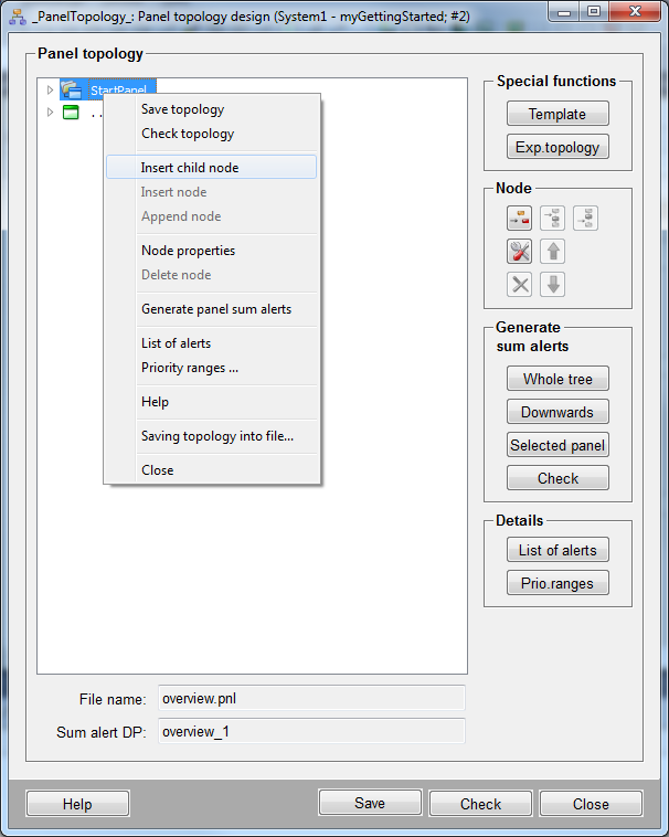
- The configuration panel will be opened.
- Configure the access to the process image with the tank system as follows (top
down):
- Enter the text "Process" in the field 'Node name:' .
- Optionally enter a description, locality, functionality of the node (here "Process tanks", "Vienna", "Fill level").
- Optionally enter the page number in teletext in the field "Panel link"(the teletext function is in version 3.8 not available yet).
- Via the open symbol, select a graphic file/icon that should be used to
identify the process image. You can find an appropriate image in the
installation directory (version)
<wincc_oa_path>/pictures/PlantIcons/process_tanks.gif - Confirm the selection 'Root' for the panel type.
- Select the file
process.pnlin the.../panels/directory through the yellow open/selection symbol under the field "Panel (incl. rel.path)" - No other inputs are necessary in the configuration dialog for the application.
- Confirm the input by clicking onOK.
- Now click on the new created node "Process " and add a further sub noden for
the trend view (
process_trends.pnl)in the same way. Also for this purpose there is already an icon available under<wincc_oa_path>/pictures/PlantIcons/process_tanks_trend.gif.
Figure 2. Specification of an Image Hierarchy in the Configuration Dialogs of the Panel Topology 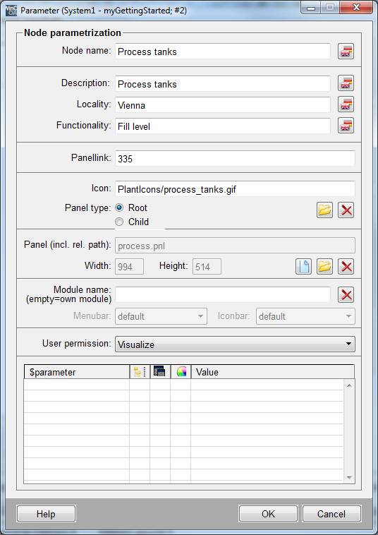
- Click in the window "Panel Topology" on the button "Template". The
following preview window will be opened:
Figure 3. The preview window "Screen configuration" 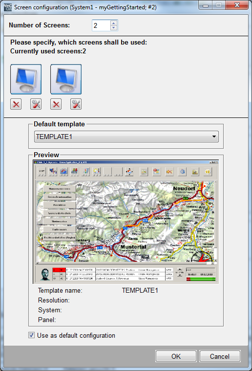
- The window "Screen configuration" serves as preview of the template and configuration of the used screens. You can define the number of screens via the spin button. These are automatically shown in the middle section of the window. Two screens are used in this case.
- In the section "Default Template" you can enter the default template, which will be selected for every screen automatically (here "ETMTREE").
- Every added screen can be configurated individually. Therefore click on the button
 of the first
screen. The configuration window will be opened:
of the first
screen. The configuration window will be opened:
Figure 4. The configuration window "Screen configuration" 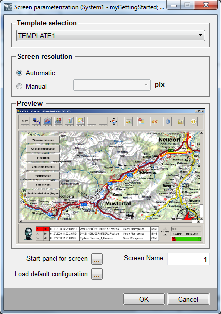
- In the configuration window "Screen configuration" you can individually select the template for every used screen via the combo box "Template selection" (here "ETMTREE"). The preview of the selected template is shown in the section "Preview".
- In the section "Screen Resolution" you can enter the resolution of the used screen manually. The resolution of the used screen will be set automatically by ticking "automatic".
- You can change the screen name by entering an alphanumeric literal (default: screen number) in the filed "Screen Name".
- Confirm the configuration by clicking on ">OK".
- Confirm the configuration in the preview window "Screen configuration" by clicking on "OK".
- A dialog box pop-ups: "Apply the configuration to all Users? Attention: User defined
configurations will be overwritten!". Confirm with "Yes", if the configuration shall
be applied. Click on "No", if a window for user selection shall be opened:
Figure 5. The window "User selection" 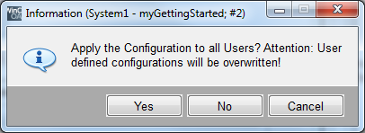
- All user groups, to which the configuration willnotbe appliedare shown in the left list of the user selection. Select the users to which the configuration should be applied and add them into the left list "Apply for".
- Confirm by clicking on "OK".
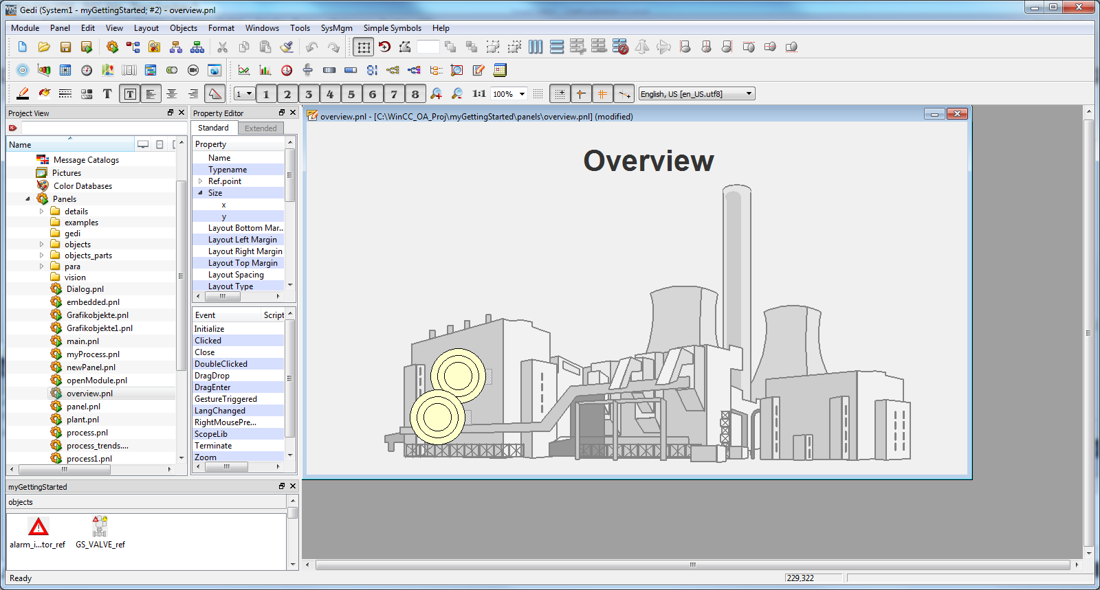
You could use the panel topology already with the settings set so far. Since in real applications an overview image is used to access the navigation and alarm view for all plant components, you will also create an overview image (see also the last figure on this page).
- Create a new panel in the graphic editor with the settings 994 x 514 pixels and save
it under the name
overview.pnlin the.../panels/directory of the current project. - Add a primitive text with the content "Overview " and adjust the font and the size accordingly.
- Draw a big rectangle (approximately 770 x 410) and fill it with the graphic
file
.../pictures/PlantIcons/powerplant.wmffrom the installation directory. - Remove the frame of the power plant view by setting the foreground color to "_Transparent".
- Set the delivered catalog of the installation directory (in case of standard installation C:\Siemens\Automation\WinCC_OA\<version>) visible using the menu View > Catalog
- Select from the catalog the symbol "PT_Sum4" under STD_PANELS and drag it to the panel area. In the configuration dialog, select the process image (Panel) "Process". It is a combined object for the display of underlying sum alarms as well as for the navigation to the associated process image.
- Proceed in the same way for another symbol and assign the earlier created trend panel (process trends) to it.
- Place the display somewhere in the power plant view and save the panel.
- Open the configuration dialog of the panel topology and click on the node "StartPanel" - select "Node Settings..." and select the created panel overview.pnl as the panel to be opened.
- Select from "Generate Sum alarms" the whole tree button .
- Save the topology again in order to integrate the new overview panel correctly.
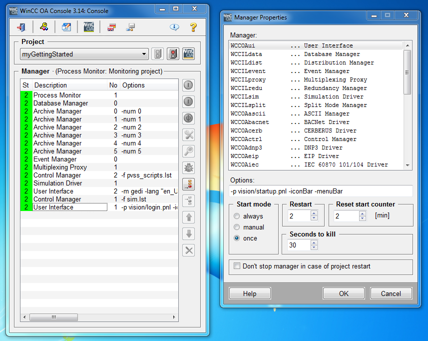
In order to use the panel topology also at runtime, you have to add a manager to the
project. You can do this using the console and ![]() append manager button. Then select "WCCOAui".
append manager button. Then select "WCCOAui".
Some settings will be passed to this manager already when it is started so that the application will be opened at the desired position (panel) without any user interaction. Additionally, the menu bar and the icon bar of the user interface module should be hidden. You can do this using the GEDI menu option Tools -> Start RunTime (<project_name>) or the call parameters:
-p vision/startup.pnl -iconBar -menuBar
Enter the call parameter exactly as here in the field 'Options ': consider thereby case sensitivity. Each gap corresponds to a blank.
The parameter "-p" (panel) shows that you have to specify the file name (and relative path) of the first panel to be shown. In our case, the used panel will be loaded from the installation directory and is always used as entry point for the login dialog.
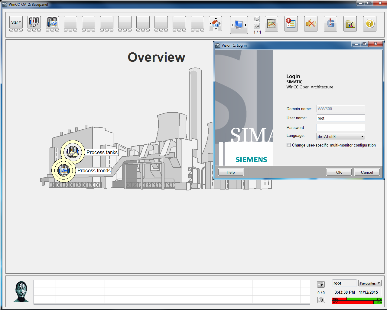
Directly after the first start of the user interface, the login dialog will be opened. By default, each new project possesses a " root " user with an empty string as password (no input necessary). The user interface will be opened by clicking on OK.
Using the start cascade (top right) you can open one of the two process images (process or process trends). You can also use the displays in the overview image to navigate to the desired process image.
In order to access the most important plant images quickly, the seven buttons next to the start cascade can also be configured online. Through [rightMouseClick] on these buttons and by selecting "Properties", a dialog for the selection of desired plant image will be opened. Select the image that should be opened using the specified button, from the hierarchy of the tree.
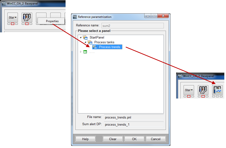
Directly after confirming the selection, the icon will be shown in the button (or if an icon is not defined, the panel name will be shown as text). Now you can open the desired process image using this button [leftMouseClick].
As soon as alarms are pending in a process image, these will be shown below the direct selection buttons. The three fields mean that these sum alarms can be divided into three different priority levels. The sum alarm displays under the start cascade serve as total sum alarm for all panels included in the panel topology.
You can also use the button Acknowledge all ![]() . If one or more alarms are pending in a process image, you can
acknowledge all alarms that are visible at that moment. If this acknowledgement does not
work, check the EventAcknowledge settings (see chapter acknowledgement
event) of all objects and generate the sum alarm again (click again on the
"whole tree" and "save" in the topology).
. If one or more alarms are pending in a process image, you can
acknowledge all alarms that are visible at that moment. If this acknowledgement does not
work, check the EventAcknowledge settings (see chapter acknowledgement
event) of all objects and generate the sum alarm again (click again on the
"whole tree" and "save" in the topology).
If you did not generate an additional overview image for the node "StartPanel", an empty panel will be used automatically. The application will then show this empty panel after the start - you can, however, navigate to the other images as already described.
In the panel topology you can also use your own, individually designed templates for the outer user interface. For more information on the panel topology, see chapterPanel topology/Group Alert Facility, basics.


