S7 - TSPP (Time Stamp Push Protocol)
General
With TSPP it is possible to transmit data from the PLC to the WinCC OA driver spontaneous and with time stamps generated in the PLC. This allows the optimization of communication since the data can be transferred only on change. It furthermore allows a better resolution of time stamps in comparison to polling because time stamps are already generated in the PLC when a value change is detected.
To use this mode some programming effort in the PLC is necessary. The PLC must prepare a defined data buffer with the data to be transferred and the PLC must send this data using a BSEND PLC function call. The structure of the data buffer is outlined below.
The TSPP data block consists of a header and several equal length records. The length of the record is defined in the header and the number of records is calculated from the overall block length.
Each record consists of
-
UTC timestamp,
-
DB number,
-
Start address, which is the address of the first word in the record and
-
The data in the following words.
An UTC timestamp must exist in the TSPP data record. If the PLC is running with local time, the time difference to UTC must be added/subtracted in the PLC during the generation of the timestamp for the TSPP record.
The size of a record is arbitrary. There can be, for example, a lot of small records or fewer large records in a TSPP block. Of course the maximum size of a BSEND function call cannot be exceeded.
The mapping of data in WinCC OA is done in the usual way. The input address mode must be spontaneous and all address types can be configured. If, for example, a record has DB 100, start address 1000 and 4 words, bit addresses of DB100.DBX1000.0 till DB100.DBX1007.7 are covered by this record.
The DB must exist in the PLC, else no communication can be established.
| Byte | Description | Meaning | Content | Format | Data Set Length | Data Length |
|---|---|---|---|---|---|---|
| 0 | TS Header | Time Stamp Protocol ID 1 | T | char | ||
| 1 | Time Stamp Protocol ID 2 | S | char | |||
| 2 | Time Stamp Protocol ID 3 | P | char | |||
| 3 | record length | n | byte | |||
| 4 | length of entire block [WORD] | (6 + n) * x | int | |||
| 5 | ||||||
| 6 | 1. record with timestamp | Date Time | SIMATIC TIME & DATE (8 Byte) |
(6 + n) [WORD] |
||
| 7 | ||||||
| 8 | ||||||
| 9 | ||||||
| 10 | ||||||
| 11 | ||||||
| 12 | ||||||
| 13 | ||||||
| 14 | DB Number | UINT | ||||
| 15 | ||||||
| 16 | Start Address | UINT | ||||
| 17 | ||||||
| 18 | Value 1 | WORD |
n [WORD] |
|||
| 29 | ||||||
| 20 | Value 2 | WORD | ||||
| 21 | ||||||
| 22 | ................. | |||||
| ... | ||||||
| ... | Value n | WORD | ||||
| ... | ||||||
| ... | 2. record with timestamp | Date Time | SIMATIC TIME & DATE (8 Byte) |
(6 + n) [ WORD] |
||
| ... | ||||||
| ... | ||||||
| ... | ||||||
| ... | ||||||
| ... | ||||||
| ... | ||||||
| ... | ||||||
| ... | DB Number | UINT | ||||
| ... | ||||||
| ... | Start Address | UINT | ||||
| ... | ||||||
| ... | Value 1 | WORD |
n [WORD] |
|||
| ... | ||||||
| ... | Value 2 | WORD | ||||
| ... | ||||||
| ... | ................. | |||||
| ... | ||||||
| ... | Value n | WORD | ||||
| ... | ||||||
| ... | ||||||
| ... | x. record with timestamp | Date Time | SIMATIC TIME & DATE (8 Byte) |
(6 + n) [WORD] |
||
| ... | ||||||
| ... | ||||||
| ... | ||||||
| ... | ||||||
| ... | ||||||
| ... | ||||||
| ... | ||||||
| ... | DB Number | UINT | ||||
| ... | ||||||
| ... | Start Address | UINT | ||||
| ... | ||||||
| ... | Value 1 | WORD |
n [WORD] |
|||
| ... | ||||||
| ... | Value 2 | WORD | ||||
| ... | ||||||
| ... | ................. | |||||
| ... | ||||||
| ... | Value n | WORD | ||||
| x | ||||||
The record length is the number of 16 bit words in a record without the 6 word record header. The length of the entire block is the number of the 16 bit words of all records (6+n)*x, where X stands for the number of all records.
If a TSPP telegram with the header "TSH" instead of "TSP" is received, the "Record Length" is interpreted as a 2 byte word. The telegram is processed as usual. Therefore, it is possible to send up to 65535-6 16 Bit Words in a TSPP record.
Configuration
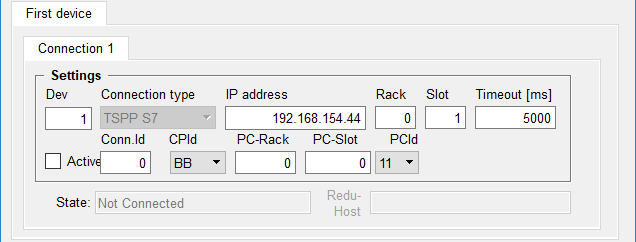
The parameters you have to define for a S7-TSPP connection in the S7 configuration panel are:
Connection type
The connection type changes automatically to "TSPP S7 connection" and cannot be changed when S7 - TSPP is active.
IP address
The IP address (or host name) of the CPU. To use a specific port, the portnumber can be stated with the IP address, e.g. "192.168.1.13:120". The default port for the S7 driver is 102.
Rack
The rack number of the CPU unit of the PLC. This has to be considered for different PLC assembles, e.g. S7-300 and S7-400.
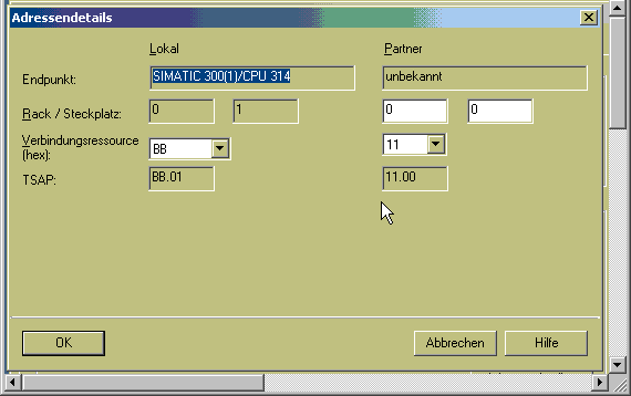
For TSPP you have to enter the number as stated in the configured connection defined via the appropriate engineering tool (e.g. NetPro or TIA portal). In this case use the number which is defined at "Address details" - "Local" and "Rack" (see also Example of TSPP configuration).
Slot
The slot number of the CPU unit of the PLC. This has to be considered for different PLC assembles, e.g. S7-300 and S7-400.
For TSPP you have to enter the number as stated in the configured connection defined via the appropriate engineering tool (e.g. NetPro or TIA portal). In this case use the number which is defined at "Address details" - "Local" and "Rack" (see also Example of TSPP configuration).
Connection Id
The ID of the S7 connection on the WinCC OA S7 driver side. This ID is only for local use.
It need not match the ID of the corresponding connection in the PLC.
CPId
The CPId must be set to the “local connection resource” specified in the PLC for the S7 connection.
PC-Rack
The rack of the PC as defined in the PLC. You have to enter the number as stated in the configured connection defined via the appropriate engineering tool (e.g. NetPro or TIA portal). In this case use the number which is defined at "Address details" -"Partner" and "Rack" (see also Example of TSPP configuration).
PC-Slot
The slot of the PC as defined in the PLC. You have to enter the number as stated in the configured connection defined via the appropriate engineering tool (e.g. NetPro or TIA portal). In this case use the number which is defined at "Address details" -"Partner" and "Slot" (see also Example of TSPP configuration).
PCId
The PCId must be set to the “remote connection resource” (or partner connection resource) specified in the PLC for the S7 connection.
For the descriptions of the other configuration parameters see Configuration of the S7 driver.
Active
This check box is used in order to set the connection to the peripheral device active or inactive. You can deactivate a connection that is already created and configured. The connection data point is not deleted and can be reactivated at any time. The status display changes from "Connected" to "Not Active"; if a connection is deactivated.
State
Shows the status of the connection to the periphery. The following states are possible:
-
"Not Connected" (Connection to the peripheral device lost e.g. PLC was disconnected from the network)
-
"Connected" (Connected with the peripheral device)
-
"General Query" (General query runs)
-
"Not Active" (Device with the associated check box set to inactive).
GQ
The General query button triggers a general query on the selected connection. For spontaneous telegrams (TSPP) this means that for the next received data the general query bit will be set. The next received data will be sent to WinCC OA (without consideration of low level comparison and smoothing). See also the config entry AutoGQ on the pagePossible config entries of the S7 driver). The driver executes an automatic general query when establishing a connection and at a redundancy switch.
The TSPP specific parameters are stored in the _S7_Config.TSPPExtras DPE.
If the S7 connection is projected through the integrated IE interface of the S7-300 controllers of the CPU31x-2PN/DP or the CPU319-3PN/DP, the FB12 "BSEND" and FB13 "BRCV" from the library "Standard Library -> Communication Blocks -> Blocks" with the family="CPU_300" must be used. These FBs can be used for the S7 communication through the integrated IE interface of the CPU as well as for the S7 communication through the S7-300 IE CPs.
If no TSPP message is received within the Alive Interval (default value 30 seconds, see Possible config entries of the S7 driver), the driver closes the connection to the PLC and re-establishes the connection. If no TSPP message is received again, the driver closes the connection again. At least one TSPP signal has to be received within the Alive Interval.
If a PLC is connected to a redundant WinCC OA system over TSPP, the Res.CPId and Res.PCId must be different for both connections. In a redundant project the panels allow to input these entries in two additional fields. These fields are visibly only in a redundant project.
Example of TSPP Configuration
On the PLC configured connections must be defined for each TSPP connection. You can do this with the STEP7 NetPro tool or TIA Portal. The next figures show such a configuration in the PLC.
NetPro
TIA Portal
Open the TIA project, go to Devices & networks and select the appropriate PLC. Go to the Connections tab of the Network view.
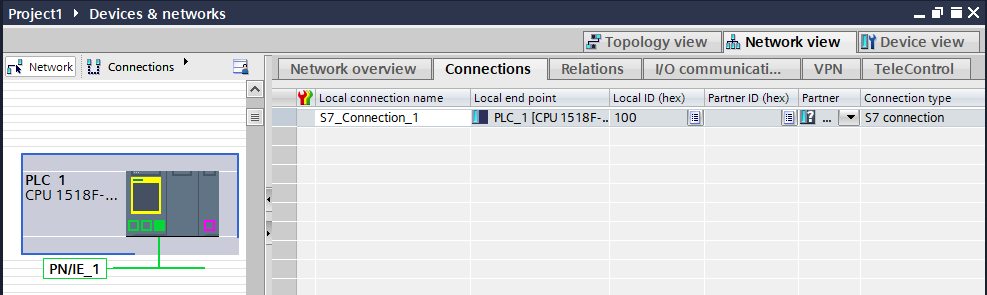
Select the connection to display the respective address details.
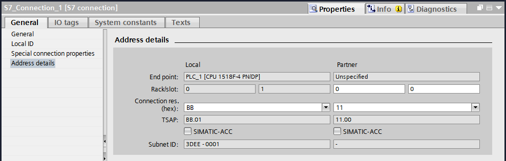
TSPP on Redundant PLC or Connection
The default behavior of TSPP with redundant PLCs or connections is that the driver picks one of the established connections to send the TSPP telegrams. These telegrams are then mapped to DPs. This means all established TSPP connections must send the same TSPP telegrams.
It is not possible for one connection to send incorrect or empty TSPP telegrams.
In this mode, there might be a loss of telegrams if the active connection is lost before the driver switches to another connection.
Using the configuration entry [s7] reduModeTSPP, set to
1 or 2, the driver can be set to accept
TSPP data from all connections. This eliminates the need for
switching connections. It allows the PLC to send empty
TSPP telegrams for an alive check, but it does not permit
sending TSPP telegrams with invalid data.
If this mode is used, duplicate values may appear in WinCC OA if the same TSPP telegrams are sent through multiple connections.
These duplicates can be filtered out using Low-Level Old-New Comparison
(Mode 1). Alternatively, if the [s7] reduModeTSPP value is set to
2, the filtering is based directly on the
TSPP telegrams.
By setting the configuration entry [s7] LimitedTSPPAliveCheck to
"Yes", you can prevent alive error messages from being
generated if the PLC does not send periodic
TSPP telegrams on all connections.


