S7 Driver Configuration
Open the configuration panel of the S7 driver via the System management panel:
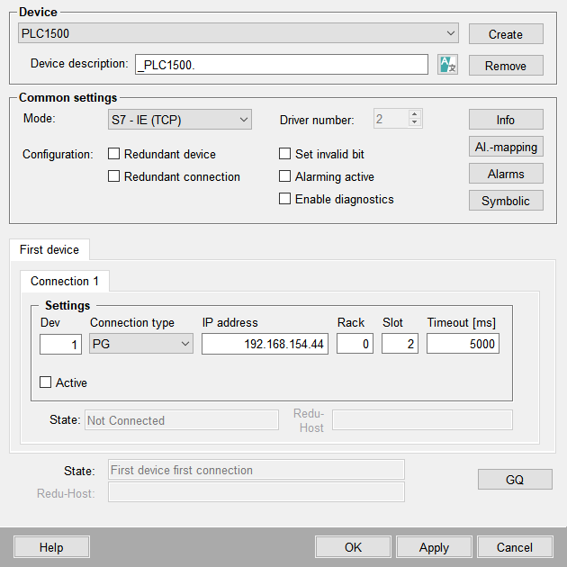
All parameters required for connection establishment like device number, connection type, rack and slot can be configured in this panel. Moreover it provides buttons to open further panels for reading information on Step 7 projects.
One internal data point of type _S7_Conn is created per device (see also Internal data points of the S7 driver).
Device
The existing devices can be selected via this combo box.
Device description
An additional description for the created device can be defined in this text field.
Create
Opens another dialog window for creation of a new S7 device. For each device a S7 device data point is created. In case of a redundant project a data point <device name>_2 is created automatically for each device data point. The *_2 data points are not visible in the combo box. After creating the S7 PLC the further parameters for the periphery can be set. These are saved in an internal data point. If the settings should be changed, choose the device name from the combo box, specify e.g. another IP address and click on Apply.
WinCC OA supports up to 512 devices. Each driver can connect to a maximum of 256 devices, therefore a second driver must be configured to connect to the devices 257 to 512,
For this the second driver has to be configured with the config entry [s7]
deviceOffset to set an offset for counting the devices
IDs, see example below. Please note that the peripherie addresses must be
configured for the corresponding driver.
Example
[s7_1] #Responsible for Devices 0 to 256
deviceOffset = 0 #default, just for demonstration purpose
[s7_2] #responsible for devices 257 to 512
deviceOffset = 256
Additional notes
-
Note that you have to configure at least one valid address (input or output) for a device so that the driver can connect to the PLC.
-
If a new connection data point is created the driver can immediately use this data point (no restart necessary). In the example above the names of the created data points will be _AG45 and _AG45_2 (in case of a redundant project).
New connection parameters (e.g. a changed IP address) will only change after the connection has been newly established, i.e. if a configuration has been set inactive and afterwards has been set active again or if a new connection has been established due to a loss of connection.
Remove
Removes the chosen device data point. A dialog box is opened, in which the deletion must be confirmed. Active devices cannot be deleted.
After deleting a S7 device it is necessary to manually delete all address configurations for the device. If the configurations are not deleted error messages will be displayed inside the LogViewer and the correct working of the S7 driver can not be guaranteed.
Common settings
Mode
Depending on the selected mode different configuration options are available. Refer to the links in the table for detailed information on each mode.
| Mode | Description |
|---|---|
| S7 - IE (TCP) | Configuration of the connection via Industrial Ethernet (TCP). |
| S7 - MPI | Configuration of the connection via Multi Point Interface (MPI) interface. |
| S7 - TSPP | Configuration of the connection via Time Stamp Push Protocol (TSPP). This mode requires special knowledge of PLC programming. |
| S7 - SINUMERIK | Connection configuration for SINUMERIK compatible devices. |
You can use different connection modes for one PLC. You have to configure one S7 data point for each connection. For example, it is possible to use Polling and TSPP for one PLC.
Driver number
Select the required driver instance number which shall be linked to the device.
The driver instance number can only be selected on creating a new device. After clicking the Apply button for the first time the driver instance number for a device cannot be changed anymore.
Configuration
-
Redundant device: Activate this check box if the peripheral device is configured redundantly. If this check box is activated, two additional tabs are displayed: Redundant device andDevice configuration. The configuration of "First device" and "Redundant device" is identical and depends on the selected mode.
-
Redundant connection: Activate this check box if the peripheral device has a redundant connection to the process control system. If this check box is activated, two additional tabs are visible: Connection 2 andConnection configuration. The configuration of "Connection 1" and "Connection 2" is identical and depends on the selected mode.
The configuration of a redundant connection is independent of a possibly existing redundant device and vice versa (you do not need a redundant connection in order to configure a redundant device)!
-
Set invalid bit: When the connection state changes from any other state to ”Not Connected”, this flag specifies whether the invalid bit should be set for all concerned input addresses in WinCC OA. This flag is also considered when there is a transaction timeout in a read or write request. This setting is stored in the DPE SetInvalidBit of the internal data point.
-
Alarming active: Enables the S7 alarming in WinCC OA. See S7 Alarms
-
Enable diagnostics: Enables the S7 diagnostic feature. The diagnostic information can be viewed within the Information Panel.
Note:Diagnostic is only available for the PLC types S7-300 and S7-400.
Info
Opens a panel which provides information on existing connections, sent/received telegrams, current configuration and last errors. For details see Information panel.
Alarms
Opens a panel for reading alert information of a Step 7 project. For further information see S7 Alarms
Al.-mapping
Opens the mapping editor to map S7 alert classes to WinCC OA alert classes. For further information see S7 Alarms
Symbolic
Allows using symbolic addressing for S7-300/400 devices: A click on the Symbolic button opens the file selector for selecting the Step 7 project (see Symbolic - S7-300/400).


