Redundant connection or device
This section provides a detailed explanation concerning the redundant configurations.
Redundant PLC
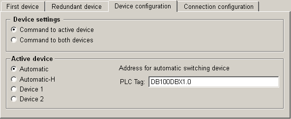
Configuration panel - "device configuration" tab
The option "Redundant device" in the common settings of the S7 configuration panel displays the "device configuration" tab. Which settings are necessary for the configuration depends on the realization of the redundant PLCs.

Device settings
Here you can define to which device a command from the control system (send direction) should be sent. Following options are available:
-
Command to active device
-
Command to both devices
Active device
This area provides settings for the definition of the active PLC in case of redundant devices. The Active PLC is considered as the relevant link. If Polling is done for certain input addresses, this is done only on the Active PLC.
-
Automatic: The driver decides which device is active. The decision is made by checking the alive status by sending of alive messages. With the setting Automatic and the definition of a PLC Tag (see below) the driver checks the defined tag (address in the PLC) which shows whether the device is active or passive. As long as the driver reads a "1" it does not switch to the other PLC. If the driver reads a "0" the driver switches to the other PLC, which should now respond a "1". If it responds also with a "0", the driver switches back again and Active link cannot be established in that case. So this mode requires synchronization between the redundant PLCs.
-
Automatic-H: Defines that device 1 is active if "0" is read from the PLC TAG, or device 2 is active if "1" is read from the PLC Tag.
-
Device 1 or Device 2: Allows to define a fix active device. This can be used for a manual override of the automatic Active PLC determination.
If either device 1 or device 2 is configured as active and this device falls out, no messages can be sent to the control system. Use this setting only for testing purposes.
-
PLC Tag: In this text field you can configure a tag in the PLC (e.g. a bit in the address space of the PLC) which signaled the active device in case of redundancy (1=Active, 0=Passive). The input of the address of this tag has to correspond with the syntax of the periphery. An example for the correct input of a tag, with syntax of the Industrial Ethernet S7 protocol, you can see in the figure above. The driver checks this tag when polling of data and thus it knows the active device. The setting of Device 1 resp. Device 2 has priority towards the PLC Tag.
Further information
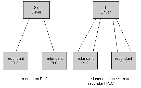
In the figure below the configuration with redundant PLCs is shown. Redundant PLCs are very similar to redundant connections. One difference, concerning the network point of view, is that redundant PLCs cannot have the same IP address. So the cases 1. and 3. of section "Redundant connections" cannot happen.
The other important difference is that the PLC address triggered switching is different, because for the redundant connection the PLC address is read from the same device (memory location), and it does not matter if connection one or two is active. If the switching between PLC is concerned the address is read either from one PLC or from the other. Therefore the method is different. If there is a PLC Tag defined the active PLC is considered as active as long as the read value is 1. If the PLC sets the value to 0, the driver tries the other PLC. The other PLC must set now the value to 1 to become the active one.

Active PLC
If a redundant PLC has been defined the driver will establish one connection to each and check the alive-status of the connection periodically as it is done for redundant connections. The active PLC is determined in accordance to the following rules.
-
The highest priority has again the manual selection of the PLC. If PLC 1 is selected manually neither the tag nor a break of connection to PLC 1 will cause a switch to PLC 2.
-
If the connection selection is defined to Automatic and no PLC Address for connection switch is defined, the driver selects the first PLC with a working connection as Active PLC.
-
If the connection selection is defined to Automatic and a PLC address for PLC switch is defined the value 1 means, that the current PLC is active and the value 0, that the driver should switch to the other PLC.
The following table summarizes the behavior:
P1 …. means PLC 1 (or first PLC).
P2 …. means PLC 2 (or redundant PLC).
The table shows the active PLC depending of working connections (columns) and selected mode (rows):
|
P1 not connected P2 not connected |
P1 connected P2 not connected |
P1 not connected P2 connected |
P1 connected P2 connected |
|
| P1 manually selected | None | P1 | None | P1 |
| P2 manually selected | None | None | P2 | P2 |
|
Automatic - No tag |
None | P1 | P2 | P1 or P2 |
|
Automatic - P1 Tag value 0 P2 Tag value 0 |
None | None | None | None |
|
Automatic - P1 Tag value 1 P2 Tag value 0 |
None | P1 | None | P1 |
|
Automatic - P1 Tag value 0 P2 Tag value 1 |
None | None | P2 | P2 |
|
Automatic - P1 Tag value 1 P2 Tag value 1 |
None | P1 | P2 | P1 or P2 |
Redundant PLC with redundant connections
This is the second case shown in the figure "Redundant configurations part 2". It is a combination of the cases described in the sections "Redundant connections" and "Redundant PLC". The active PLC is determined in accordance to the rules described in "Redundant PLC" and the active connection is selected as described in "Redundant connections". For switching the connection the corresponding PLC address tag is only used from the active PLC.
Redundant connections
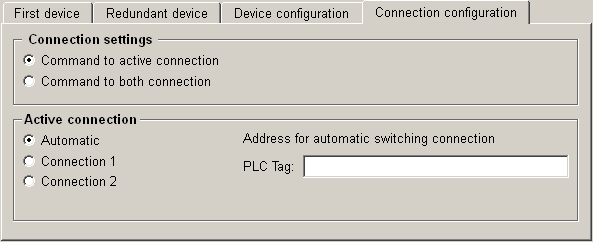
Configuration panel - "Connection configuration" tab
If the connection to the devices is configured redundant you have to configure the connection on the Connection configuration tab:

The settings you can make on this tab are the same as described before on the Device configuration tab. The difference of these settings is the configuration of redundant connections, contrary to redundant devices.
Furthermore you have to consider that if you define a PLC tag when configuring the connection, the interpretation of the driver is different. The tag defines again an address in the PLC (e.g. a bit). The value of this bit finally defines the connection which the driver selects, e.g. 0 is the first connection, 1 is the second connection. The value, i.e. the selected connection, can be different on the devices.
Further information
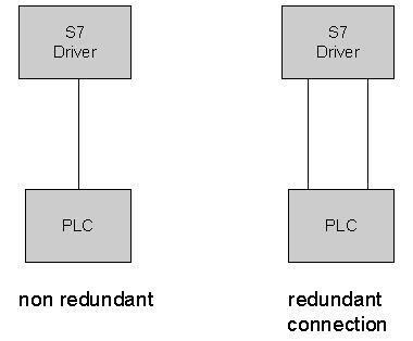
The figure below shows the normal (non redundant) case and the case with redundant connections to one PLC.
In the normal configuration (neither redundant PLC nor redundant connection, see first case in the figure below) the S7 driver establishes two read and one write link to the PLC. If the config entry "[s7] UseConnections" is activated, only one link is used for reading and writing. The latter case might be better for old S7 300 equipment, which are very limited in available connections.

The second case in the figure above shows the configuration with redundant links. For this case the several cases can be distinguished.
-
The host running the driver has only one network address and the PLC has only one CP. The case is not very useful because both connections will probably break at the same time if anything happens in the network.
-
The host running the driver has only one network address and the PLC has two CP (i.e. two IP addresses). This is a useful configuration, because a problem with one CP or on the link to one CP might be recovered.
-
The host running the driver has two network interfaces (IP address) and the PLC has one CP. This is not useful in the moment, because in that case we cannot determine in the driver which route is used to the PLC. Because it might probably be that both connection take the same route to the PLC, which means that both will fail if a failure in the network appears.
-
The host running the driver has two network interfaces (IP address) and the PLC has two CPs (i.e. two IP addresses). This is the most useful case, but it must be considered, that if the two connections are not separated into 2 subnets, a proper routing must be set up on the S7 Driver host, which makes sure, that different connections are using routes via different network cards.
Active connection
If a redundant connection has been defined the driver will establish the two connections and check the alive-status of the connection periodically. For this purpose it is important that the alive checking is not turned off via the "AliveInterval" config entry. Otherwise lost connections are not detected. The active connection is determined in accordance to the following rules:
-
The highest priority has the manual selection of the connection. If connection 1 is selected manually neither the tag nor a break of connection 1 will cause a switch to connection 2.
-
If the connection selection is defined to Automatic and no PLC Address for connection switch is defined, the driver selects the first working connection as Active connection.
-
If the connection selection is defined to Automatic and a PLC address for connection switch is defined, the value 0 selects connection 1 and 1 selects connection 2.
The following table summarizes the behavior:
C1 ... means connection 1 (or first connection).
C2 … means connection 2 (or redundant connection).
The table shows the active connection depending of working connections (columns) and selected mode (rows):
|
C1 not connected C2 not connected |
C1 connected C2 not connected |
C1 not connected C2 connected |
C1 connected C2 connected |
|
| C1 manually selected | None | C1 | None | C1 |
| C2 manually selected | None | None | C2 | C2 |
|
Automatic - No tag |
None | C1 | C2 | C1 or C2 |
|
Automatic - Tag value 0 |
None | C1 | None | C1 |
|
Automatic - Tag value 1 |
None | None | C2 | C2 |


