S7 Alarms
With the help of the WinCC OA S7 alarming, alarms which up to now were only known in the PLC can be triggered and acknowledged in WinCC OA. I.e. by an acknowledgement in WinCC OA the alarms are also acknowledged in the PLC.
Requirements
-
An S7 project with configured alarms is available
Note:Only Step 7 project files (*.s7p) can be used. -
The WinCC OA project is started
Notes & Restrictions
-
S7 alarms are only supported under Windows!
-
S7 alarms are only supported for S7 PLCs with an S7-IE (TCP) or S7-MPI connection
-
Symbol-related alerts (SCAN alerts) are only supported for S7-400 PLCs, but not for H-PLCs
-
Only the CPU-wide project engineering procedure is supported, but not the project-wide
-
The following alarm data blocks are supported:alarm, alarm_8, alarm_8p, alarm_s, notify, notify_8p - in acknowledgeable (e.g. alarm_sq) as well as in unacknowledgeable form
Alarm data blocks configured in CFC are not supported by WinCC OA. Use other function block programming languages like LAD, FUP or SCL.
-
Set the debug flag "-dbg alarm" to get detailed information on S7 alarming
-
S7 alarming can be deactivated due to performance reasons with the config entry "connectForAlerts" in the [s7] section.
-
S7 alarming is supported with a WinAC (PCS7 Box Industry PC) but not with a WinLC (Soft-PLC)
This describes step by step how to map S7 alarm classes to WinCC OA alarm classes, to receive alarms and to acknowledge them.
Configuration of the S7 driver
The basic configuration of the S7 driver is carried out according to the description in the chapter Configuration of the S7 driver. It is assumed that a device was created and all relevant connection settings have been set. In order that the S7 driver can also receive alarms, the following settings must be performed in the S7 driver configuration panel:
Activation of the alarming
Check the checkbox Alarming active in the Settings area.
Alarm configuration
Once a station was chosen, all contained S7 alerts are read out and listed in the table below. For every listed alert the alert number, signal number and alert text are displayed. Once the device is connected to the station (can be connected via a checkbox) the S7 driver can receive alerts from the PLC.
-
Click on the Alarms button in the S7 driver configuration panel.
-
This opens a file selector. Select your S7 project (*.s7p) and click on Open to confirm. Please consider, that the name of the S7 project must not contain any other character than "A-Z","a-z", "1-9" or "_".
-
This opens the alarm configuration panel and the alert configuration from the S7 project is imported automatically.
Figure 1. Figure: Alarm configuration with example data 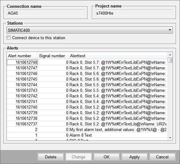
-
Choose from the Stations combo box the station from the S7 project, with which the S7 driver according to the connection settings (IP, Rack, Slot) is connected, and check the checkbox Connect device to this station. (With the button "Change" it is possible to change the selected station).
-
Click on OK to complete the alarm configuration and thus to create automatically the data point _S7_400_s7400Hte_SIMATIC400 of the type _S7_AlarmParam. The data point name is composed of the device name , the S7 project name and the station name.
-
To delete an S7 alarm configuration, click on Delete. All alarm configurations will be deleted and a new Step 7 project can be read.
Mapping of alert classes
-
Click on the Al.-mapping button in the S7 driver configuration panel to map S7 alert classes to WinCC OA alert classes.
-
This opens the Alert class mapping panel.
Figure 2. Panel for mapping S7 alert classes to WinCC OA alert classes 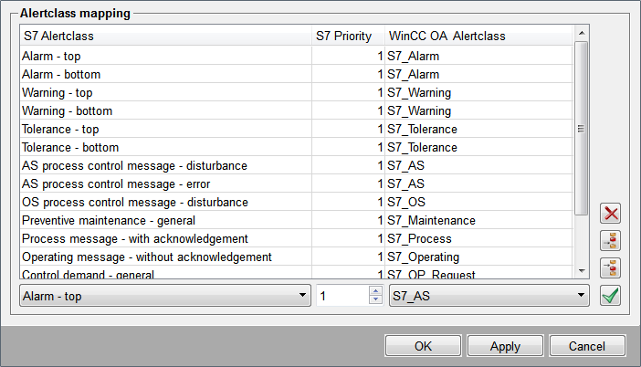
-
All existing S7 alert classes (altogether 16) are listed in the S7 Alertclass column. For each of these 16 alert classes a priority from 0 to 16 can be assigned. Together they are mapped to the WinCC OA alert class.
-
By default there are 13 WinCC OA alert classes with the prefix S7_* available in WinCC OA and are mapped adequate to the S7 alert classes.
-
Beneath the table with the alert priority mappings 3 fields can be found (two combo boxes and one spin button in the center). By them the alert class mapping can be changed.
-
To change a mapping, click on the corresponding line with the S7 alert class to be changed, set the new priority by using the spin button beneath the S7 Priority column and select a WinCC OA alert class from the combo box beneath the WinCC OAAlertclass column, which should later represent the S7 Alarm in the WinCC OA alert screen. The new WinCC OA alert class can be another than one of the predefined alert classes for S7. You can also create your own alert classes. To apply the changes in the alert class mapping to the table click
 .
. -
To delete an alert class mapping, click on the corresponding line in the table and then on
 .
. -
To add an alert class handling to the table, select a line in the table and click on
 to insert a copy of the
selected line below it, or click on
to insert a copy of the
selected line below it, or click on  to insert a copy of the selected line above it.
Alert handling and definition of the peripheral address
The alert handling (_alert_hdl) is carried out using multiinstance alarms (see Alert handling for multiinstance alarms) and must be added to the corresponding data point element. Multiinstance alarms do not depend on the original value of the data point element, but react to the values received from the PLC.
At the same data point element, an S7 peripheral address config (_address) with the S7 address type Alarm Address must be added, so that an S7 variable can be chosen which triggers the alert. The S7 variable is composed of the name of the data block and the alert identifier, e.g. "Anlage13_Motor42.Error".
To receive hardware errors on a DPE, the special variable @SystemErrors@ can be chosen.
If the S7 variable belongs to a symbol-related alarm, an "$" is appended to the peripheral address string.
The alarming is enabled if the checkbox Address active (at the bottom of the panel) is checked.
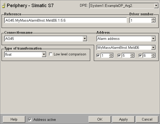
Optionally, there is also the possibility to write the S7 additional value to the original value of the data point element or to write the information text and additional text of the S7 alarm to the additional values of the WinCC OA alarm. This can be set via check boxes and spin buttons below the S7 variable selection (from left to the right):
-
Defines whether the S7 additional value with the number here defined (default = 1) is mapped to the original value of the DPE. If yes, check the check box.
-
Defines the number of the WinCC OA additional value to which the info text from the PLC is mapped.
-
Defines the WinCC OA start additional value from up the additional texts from the SPS are written to. Per alert text there are exactly 9 additional texts.
Format and example of the extended peripheral address:
<PLC variable>:<additional value original value [0..432]>:<additional value for info text [5..]>:<start additional value for additional texts [5..]><$ if symbol-related alarm>Plant13_Engine42.Error:1:5:0-
The original value is set from the 1st additional value of the S7 alarm
-
The info text is set to the 5th additional value of the WinCC OA alarm
-
Additional texts are not written to the additional values of the WinCC OA alarm
Acknowledgement of alarms
In order that alarms are not acknowledged directly in WinCC OA but via the S7 PLC the following procedure is required:
-
Individual alarm classes with a unique prefix must be created in the project.
-
In the config file of the client project the following entry must be set.
[driver]
driverAckClassPrefix = "<prefix>" //e.g. "S7"
This entry is read from the UI and leads to acknowledgement of the alarm not via the Event manager anymore but via the internal driver data point _ DriverCommon (see driverAckClassPrefix). Only if the PLC sends the confirmation of acknowledgment to the S7 driver, the alarms will be also acknowledged in WinCC OA.


