Principle and functionality
In normal case a redundant system consists of two projects on different computers with same operating system. The same managers run on these both systems, which are provided with a redundant network connection. The redundancy is mostly hidden for the managers and the managers act as in a simple system. Actually, the data stream and dynamic are checked and controlled via the system messages of the Event Manager.
In a redundant system single system components can be controlled and provided with
weighting, which is used for calculating the error status in case of errors. Components
that are controlled and used when calculating the error status are e.g. managers, TCP
connections, PLC connections, hard disk capacity, RAM memory etc. The weighting is a
number from 0-999, which the user can assign specific to the components. The person who
configures makes the decision how grave an error is, meaning which number is specified
for the weighting. The crash of a PLC connection is e.g. configured with a higher
weighting as a crash of a UI. In normal case the sum of the weightings that produce the
error status should be same on both computers (optimal is the error status 0). In case
of errors the computer is automatically switched. This means the active computer is
always the computer with the lower error status. The error calculation is executed in
the CTRL script calculateState.ctl(this script is contained in
pvss_scripts list). The configuration and error
weighting are executed in the system overview panel. For further information see System overview panel in redundant
systems.
The redu manager (WCCILredu) executes further important functions in case of a redundant system (the default number of the redu manager is 4776). The redu manager has the following tasks:
- Redundancy state: The redundancy status (which computer is active and which is passive at the moment) is defined and given by the redu manager since the redu manager keeps all information (internal system statuses) of itself and of its partner. Furthermore the redu manager manages the error statuses of itself and of its partner. These statuses are compared to each other and the computer with the lower error status becomes automatically active (the Event Manager switches the active/passive status of the computers).
- Exchange of system information and alive messages
- Analysis of partner crashes.
The following figure should visualize the principle of the redundancy a little better:
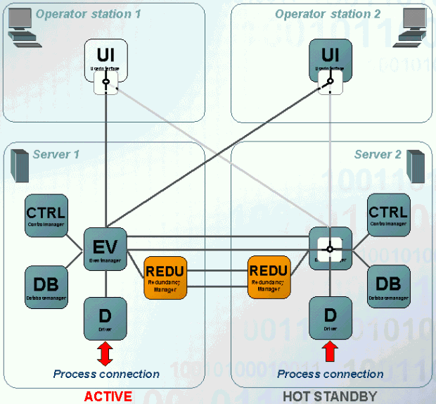
The figure shows a detailed presentation of both computers Server 1 and Server 2 as these are already known from the figure on the page redundancy, basics. Server 1 is in the control mode (active) and server 2 is in the hot standby mode (passive).
The UIs of the operating terminals are connected to both Event Managers in redundancy case. However, only data of the active system is shown on both UIs. The Event Manager of the passive system is restricted to communication with the Event Manager of the active system for balancing of the process data (it does not send any data to the connected UIs or discards the messages of the drivers. You can see this in the figure with the switch in the UIs or at the passive Event Manager.
The message logic (messages and commands) is illustrated via the following figures:
Driver message
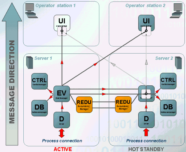
The message in the message direction is processed as follows:
- Both drivers receive a message from the periphery (this does not always happen since the driver receives the different values at different times when a polling is configured. This means that the driver receives a message only on one computer). On the active system the value is passed to the Event Manager and the passive system discards the message.
- The Event Manager on the active system sends the value to all registered managers. Via the redundant network connections the value is sent to the passive Event Manager. On the passive system again the value is sent to all managers registered at the Event Manager.
- The value is sent to UI`s of both operating terminals only by the active Event.
The same behavior also applies for values, which are sent by other managers (e.g. CTRL, API)!
Driver command
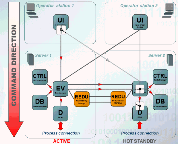
The message in the command direction is processed as follows:
- A value is changed on the UI of the operating terminal 1. The change is sent to the Event Manager of the active system. The passive Event Manager does not accept any change from UI.
- The Event Manager on the active system sends the value to all registered managers. Via the redundant network connection the value is sent to the passive Event Manager. On the passive system the value is passed to all managers registered at the Event Manager.
- The value change is passed to the periphery via the driver on the active system. The driver on the passive system discards the value changes and does not pass any data to the periphery.
This behavior in the command direction applies specific only for driver!
Since the database is identical on both computers the same DPs exist on both computers. These DPs always have the same value and name on both computers. For the DPs described so far (in the command and message direction) this was wished. The behavior of the message logic in the message and command direction was already described in the previous paragraphs.
Furthermore, there are data point elements for internal states (e.g. disk space, RAM memory, connection to the peripehery, ...) . The information of these data point elements may be different on both computers and has to be known on both computers. This case is solved different in the redundancy:
- DP`s containing Information for internal states exist twice with different names (once with the Postfix "_2" and once without postfix) on each computer.
- The left computer is responsible for data point without postfix, the right computer sets the "_2" data point. Assuming that the S7 driver looses the connection to the periphery the element _S7_Conn.ConnState would be set on the left computer in case of normal driver logic (left computer is active, right computer is passive). If connection would be lost on the right computer this would discard the value (since it is passive) and the "_2" data point is not set. So that this kind of behavior does not occur there are so called "Forward DPs". Forward DPs are set and passed to other computers (the DPE _S7_Conn.ConnState is a such forward DP). Thus, it can be guaranteed that the information is always available on both computers.
- The data point _S7_Conn does, however, not only consist of the element .ConnState but also of elements, which contain configurations or trigger commands (e.g. _S7_Conn.DoGeneralQuery, _S7_Conn.UseTSPP, _S7_Conn.ProjectName, ...). The value of these DPEs should be identical on the left and on the right computer in normal case. So that such DPEs are identical on both computers there are so called "Copy DPs". Copy DPs adopt the set value to the DPEs of the both computers. Thus, if the e.g. the element _S7_Conn.UseTSPP is set to "1" the value "1" is also set on the element _S7_Conn.UseTSPP.
Settings concerning forward and copy DPs (especially in case of project specific
adjustments) are executed in the configuration file
config.redu in the directory
<proj_path>/config(see also configuration files for redundancy).
With the key word "fwdDpType" (like fwdDp) all changes on this DP element are passed from the Event Manager automatically to the redundant Event Manager. Contrary to "wdDp" a DP element of an existing data point is not specified but the element of a DP type in the form "Type.Element" (e.g. "ExampleDP_Bit." for the root element of the DP type "ExampleDp_Bit"). Thus, the corresponding elements of all data points of this type are forwarded.
Split mode at redundancy
The split operation at redundant systems is a separation of both redundant servers whereas one server remains active. The second server can be used for tests of new configurations and configurations. The advantage is that this can be executed at runtime on a plant without adverse effect on the active system.
You can freely choose which system remains active when using the split mode (switching the UIs to this system) and which system is used for test purposes. After finishing the tests the system returns to the redundancy operation on the basis of a system. This means that if the test was successful the system is synchronized with the control system when the system returns to the redundancy mode and the new configuration is used on both systems. If the old system should remain redundant the test system is synchronized with the control system and the redundancy runs with the settings, which existed before switching to the split mode.
For detailed information on the split mode see chapter System overview in redundant systems and Redundancy in split mode.
Redundancy behavior of the passive event
The redundancy behavior in WinCC OA provides that value changes on the passive event will not be discarded until it is not sure that the active event processed/passed them.
Good case:
Time Stamp   Event Manager (1|2)   Description
------------------------------------------------------------------------------------

10:00:00     Event 1(active)       Gets value change 1
10:00:01     Event 2 (passive)     Gets value change 1
10:00:02     Event 2 (passive)     Ignores value change 1
10:00:03     Event 1(active)       Processes value change 1 and passes it to Event 2
10:00:22     Event 2 (passive)     Discards value change 1
Critical case - Breakdown of the active event:
Time Stamp   Event Manager (1|2)   Description
------------------------------------------------------------------------------------
10:30:00     Event 1 (active)      Gets value change 2
10:30:01     Event 2 (passive)     Gets value change 2
10:30:02     Event 2 (passive)     Ignores value change 2
10:30:03     Event 1 (active)      Breakdown -> no passing to Event 2!
10:30:13     Event 2 (passive)     Detects the breakdown of the active event and processes all value changes, which have not been processed yet
10:30:14     Event 2 (now active)  Processes value change 2
Taking sender into account
As this behavior of the redundancy should only be used in case of a failure (breakdown, disconnect, etc.), the sender of the value change is also taken into account.
Time correction in case of the same sender
When in the process image is saved that the last vale change was sent by driver 1 with the time stamp 10:00:01 and the currently processed value change by the event has been also received from driver 1, but with the time stamp 10:00:00, then a time correction is used instead of this redundancy behavior. Time correction means that the time stamp will be corrected to <last_value_change> + 1 millisecond (in that case 10:00:00 + 1 millisecond).
Different senders
When in the process image is saved that the last vale change was sent by driver 2 with the time stamp 10:00:01 and the currently processed value change by the event has been also received from driver 1, but with the time stamp 10:00:00, the event detects that a redundancy switch had been executed and discards this value change.
Simultaneous value changes and general query
Simultaneous value changes from different drivers (senders) will be discarded.
In case of a general query all values, which have not been changed, will be send with the same time stamps, what may happen that they will be discarded by this redundancy behavior. Thus this redundancy behavior will not be used in case of a general query.
Time difference between redu partners
Each manager checks the time difference between the redu partner (refer to valueChangeTimeDiff). The result is written on the connection-specific data point _ManagerConnections.TimeDiff. If the maximum time difference is exceeded the connection is closed by the manager and a correpsonding message is displayed in the LogViewer.


