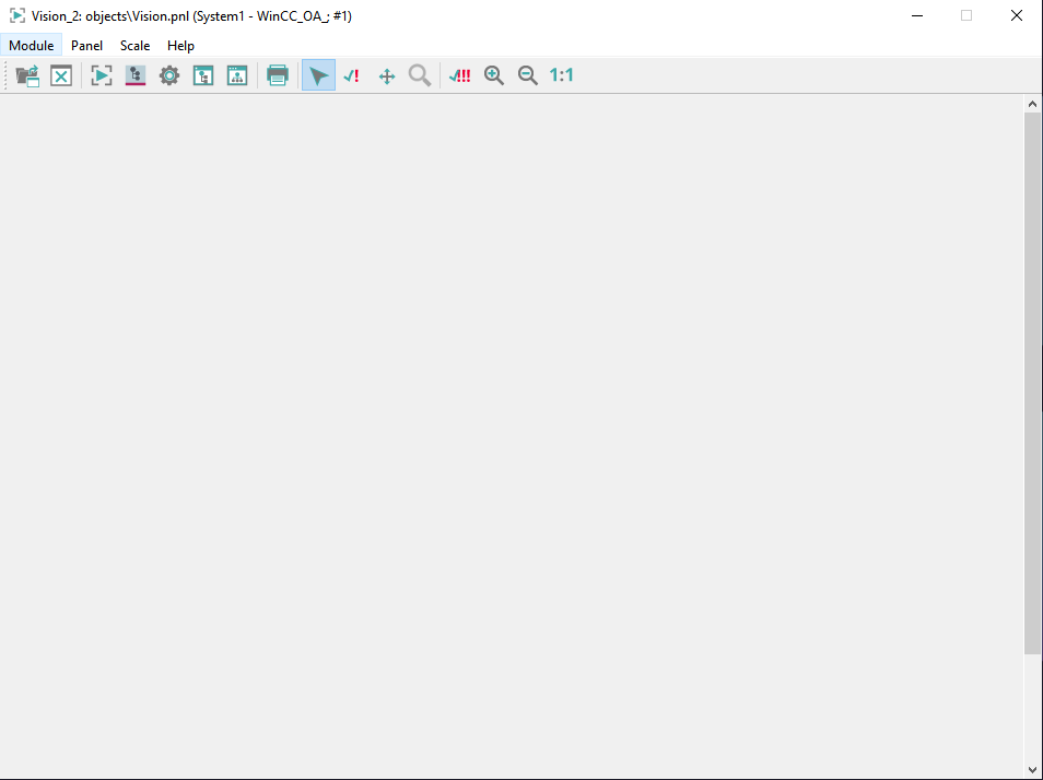
Structure of the User Interface (VISION)
The module VISION comprises four menus and an icon bar. The menus contain the same functions as the icon bar (buttons). For the description of the buttons, see the description of the menus.
which are described in the following.
Note:
A panel can also be specified as a start option e.g.
WCCOAui -p
para.pnlModule menu
Via the module menu you can:
- Open the graphics editor GEDI. The graphics editor is used to create and configure panels. System diagrams, detailed representations or input screens can be modified or created using the graphics editor. Refer to chapterGEDI for further information.
- Open a panel in the module VISION. The panel selector is opened. Only one (root) panel can be opened in each VISION module. Any number of (root) panels can be displayed, however, by having several VISION modules open at once.
- Open the PARA module. The PARA module is used for assigning new attributes to data points, such as conversions, a smoothing or alert handling procedures, as well as creating new data points and data point types. Refer to chapter Module PARA for further information.
- Open the System Management panel. The panel is used for the administration of a WinCC OA system. Refer to chapter System management for further information.
- Open the Panel Topology. Panel topology means that all panels in a project are organized into a hierarchy. This structuring simplifies the project enormously, especially when dealing with large process installations. Special functions then check the constructed topology (e.g. panels can be accessed using buttons as defined in the panel topology). Refer to chapter Panel topology/Group alert facility for further information.
- Open the Plantmodel Editor. The Plantmodel Editor can be used for building and modifying data structures based on CNS. Therefore, views and trees can be created and used within the project easily. Refer to chapter Plantmodel Editor for further information.
- Close the current module (Close Window).
- Close the user interface (Exit).
Panel menu
Via the panel menu you can:
- Open a panel. The panel selector is opened. The project directory "panels" is opened by default. The panel selector allows you to select a directory under "Project level" and then the required panel. If the panel cannot be displayed in full in the module then scrollbars are added to the module for revealing the hidden parts of the panel.
- Close a panel. The open panel is closed.
- Print a panel. The standard print dialog is opened. Here you can make the settings.
- Copy the image of the current panel into the clipboard.
- Activation mode. The module must be switched back into operating mode after individual or common acknowledgement of alarms in the panel. To do this select this option. An easier way is to click on the "Activation mode" icon in the icon bar.
- Acknowledge an alarm (Single confirmation mode = acknowledge a single alarm).Critical system statuses are generally represented by colored surrounds or flashing graphics elements. In many cases the operator of the process control system must confirm these status indicators. This can be done by clicking on a button in the icon bar for acknowledging alarms, by clicking on the flashing graphics elements themselves or by clicking on the relevant line in the alert panel. If several indicators requiring acknowledgement occur, it may be specified that some of them can be acknowledged jointly (see the option common confirm below), while others must be acknowledged individually because of their significance. In order to individually acknowledge status indicators by clicking on graphics elements rather than the alert screen, the VISION module must switched to Acknowledgement mode. To do this select the option "Single Confirmation Mode" from the Panel menu. An easier way is to click on the Single Confirmation Mode icon in the icon bar.
- Move a panel in the module without using scroll bars (="Panning"). A white hand symbol is visible if you use this function. In order to activate this function, use the function ModuleOn() and the parameter "Zoom".
- Zoom a panel (zoom mode). In order to activate this function, use the function ModuleOn() and the parameter "Zoom".
Note:
The functionality of WMF and especially EMF graphics under Linux is limited since
the whole functional range is not available.
- Acknowledge several alarms (Common confirm). Several alarms are acknowledged at once. Some graphics elements may continue to flash if the acknowledgements required cannot be performed by this means; the indicators in question must then be acknowledged individually. (see Single confirmation mode above).
Scale menu
Via the scale menu you can:
- Zoom panels in
- Zoom panels out
- 1:1 - set the original size of a panel
Note:
All objects can be scaled!
Help menu
Via the Help menu you can:
- Open the different chapters of the Online Help (GEDI - GEDI, basics, PARA - PARA module basics, Control Programming - Introduction to CTRL).
- About QT shows you information about the QT toolkit. The toolkit the WinCC OA user interface is based on.
- About WinCC OA shows you the ETM address information.


