Setting the OPC Client
In order to establish a connection to an OPC server, you only need to execute few steps. In the following instruction, the parts that are specific for the used controller or dependent on the server installation were highlighted green. For an OPC connection to other devices, adapt these accordingly.
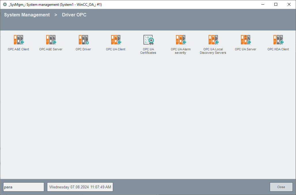
- Open the System Management Panel using the toolbar
 of the graphic editor
GEDI.
of the graphic editor
GEDI. - Switch to the Driver tab and click on the OPC Driver.
- In the opened dialog, configure the OPC server - you can select already configured OPC servers from the combo box "Server name" on the top right. Temporarily, ignore the both "EXAMPLESERVER".
- Click on the Create button to configure another OPC server (installed on the
computer) for the project.
Figure 2. Selection of an OPC Server from the List of the available Servers 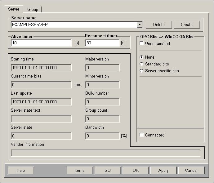
- After clicking on Create, all available servers will be shown in the list of the available (installed) OPC servers.
- Click on the favored OPC server.
- The configuration data of every OPC server that is used in a project will be saved in an internal data point. A name will be shown automatically for this internal data point in the field "data point name". You can also change this manually.
- Confirm the selection with OK. The administration data point will be created
automatically. A dialog shows which entry has to be added to the config file of
the project.
Figure 3. 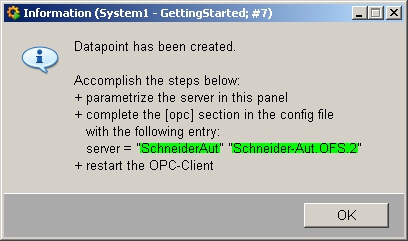
- Switch to the console and open the config file of the current project using
the
 button. Alternatively you
can also open the file
button. Alternatively you
can also open the file <proj_path>/config/configin a text editorthrough the file system. - Enter the configuration text to the file exactly as shown in the dialog.
Consider the case sensitivity.
Figure 4. 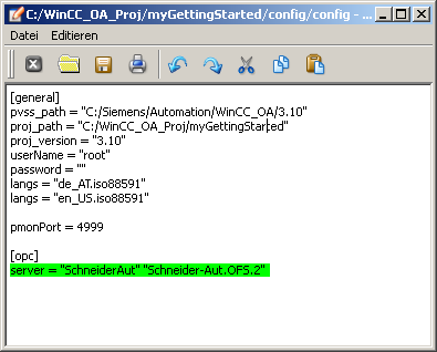
- Save the config file. Enter the associated OPC client as a managerto the console. In addition, stop the simulation driver "Sim" if the new OPC client should run using the driver number 1.
- Switch to the console and change the start mode of the simulation driver (WCCILsim) to "manual".
- Stop the simulation driver (WCCILsim).
- Add a new manager "OPC DA Client" (WCCOAopc) through
 to the manager list of the console.
 - Start the OPC DA Client (context menu [rightMouseClick] > Start manager or use the green start button next to the manager list on the right).
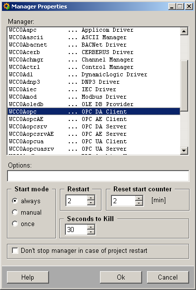
The OPC client runs and is able to start a correctly configured OPC server automatically. The correctly running client will be shown with state color green ("2") in the console.
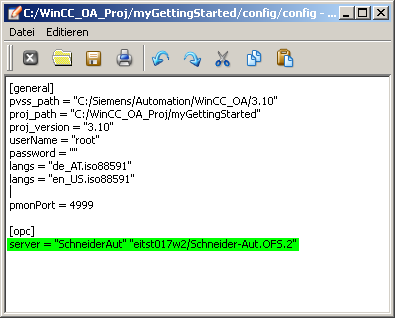
If the selected OPC server would run on a remote computer and if the remote communication through DCOM would have been selected, the entry in the config file would also contain the computer name (shown in the next figure "eitst017w2"):
The connection to an OPC server running on a remote computer may be dependent on the security settings of the operating system. If the list of available servers is not shown when entering the remote computer or if problems occur later, see chapter DCOM Configuration for OPC Client-Server Connection.
You can view the connection state or the server state subsequently via the System Management drivers tab and click on the OPC driver button. Select the appropriate entry from the combo box "Server name:" - in the current example, the entry is "SchneiderAut".
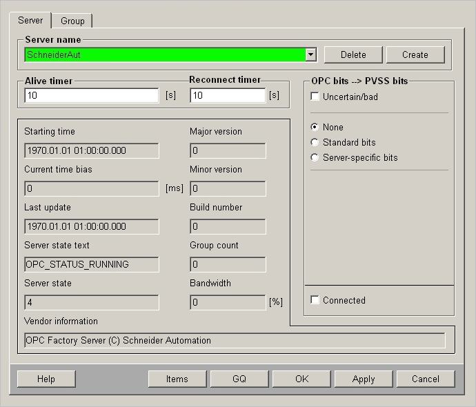
Consider that the OPC client shows at least the following states for the server (see following figure) in case of a correct connection:
-ServerStateText = "OPC_STATUS_RUNNING"
- ServerState = 1
- Last Update = approx. current time
All shown states or hierarchy descriptions on the "Server" tab are standardized by the OPC Foundation and should be shown accordingly in English with the quoted notation in each product.
You have now specified an OPC server for a driver connection and started an OPC client. Now you have to define the communication parameters and combine the individual data points with the appropriate elements of the periphery. According to the hierarchy model of OPC, the communication parameters will be specified consistently per connection group (OPC group). Therefore, you will first need such a OPC group. The OPC client in the server may create and configure it.
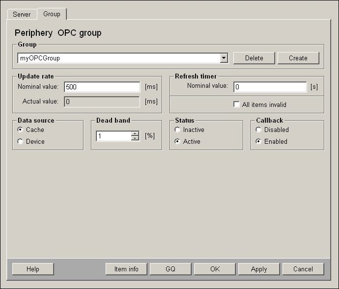
- Switch in the OPC Configuration panel (System Management) to the "Group" tab.
- Enter a new group name into the Combo box, for example, "myOPCGroup" (overwrite thereby the description of the group existing by default).
- Click on Create in order to create the group in the server.
- Set the connection parameters as shown in the figure above (the data only
contains the differences):
a.) Update Rate > Reference: > 500 [msec] ("0" would mean "as fast as possible for the server")
b.) Status > Active c.)Callback > Enabled
- Confirm the communication settings with click on OK.
To configure an individual data connection between a data point element in WinCC OA and a process variable in the underlying controller, add an address config.
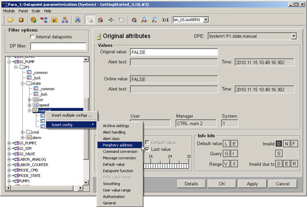
- Open the module PARA and select the data point element that should present the value of the periphery.
- Add the config to the data point element through the context menu [rightMouseClick] > add config > peripheral address.
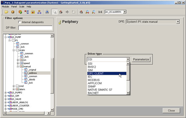
- Select the config "_adress" and select the driver "OPCCLIENT" from the view on the right and click on Configure...
- Now a dialog for setting the peripheral address for the selected driver type is opened.
- Select the configured OPC server (see figure above), the group name (see figure above) and item address. Enter the data direction and activate the "low level old /new comparison". The data direction "In" means that the value will be read from the controller, meaning it presents an input.
- In most cases you can keep the "default" setting for the transformation type. Merely if you use some specific servers or if you transform data types, you can enter a data type here.
- Activate the check box for "address active".
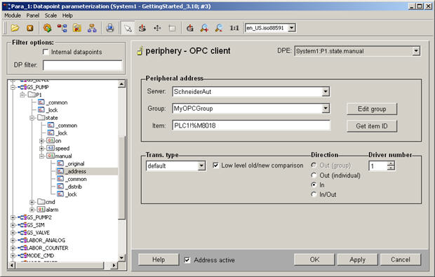
The specified item name "PLC1!%M8018" is composed of two parts. "PLC1!" is a prefix that was assigned individually when configuring the server. The second part "%M8018" corresponds to the common direct addressing on the target device (flag 8018). This is a device-specific address part.
For the OPC, you can prepare the item names through a specific service of the server so that you only have to select them when configuring. Depending on the demonstration in a list or a tree structure, it is either flat or hierarchicalbrowsing. Consider that all servers do not support hierarchical browsing. You can browse the existing items by clicking on the Get Item ID.For more information on the OPC driver, see online helpOPC, Basics.
Mostly, the OPC servers can provide the whole direct addressable data room without setting this visible for the item browsing. According to the server-specific prefix, addressing are "%QX0.0" or "%MW731" for IEC61131 or "DB100DBW20" for Simatic S7. Also for the used example of the Schneider OPC server, directly addressed items can be used without providing these through the browsing interface.
For the data point type pump, no master data point was used. Therefore, you can assign different configs for each element of each data point instance. Also the earlier added peripheral address for the connection with the OPC server was simply added as config for an element of an instance.
If you would use the object-oriented way for the valve type, you would add the address as a PowerConfig to the master data point. Thereby, you can not only select the drivers but also some specializations. The address string assigned to the master data point can be regarded as default configuration for all instances. Through [rightMouseClick] on the element of an instance and selection of "Configure PowerConfig", you can set an address individually.
You won't assign the address in the PARA very often (as well as all other configurations) but usually as mass configuration in table form, for example, in MS Excel (see also Import from ASCII file (Mass Engineering) or Create Data Point Lists).
When using a remote OPC server, consider that the system time of the remote computer corresponds to the time of the WinCC OA system!
Whenever you want to establish an OPC connection to a remote computer, it is advisable for the operation to run the WinCC OA OPC Client remote on this computer. Thereby, you can use the secure WinCC OA TCP connection instead of DCOM.
Without specific measures, the driver adopts each new value and updates the process image in the event manager. This also applies when the value has not changed since this is of importance for some spontaneous working peripheral systems. When using controllers (PLCs), at least the old-new comparison is activated in the driver (see also the specific figure above). This setting guarantees that only changed values will be adopted in the process image. This change must not consider the value itself, the value is also adopted when the state (quality) changes.
To limit the dynamics to a meaningful degree in case of processes with high change rates, WinCC OA provides smoothing possibilities. By adding a smoothing config to a data point element, you can use more significant time or value dependent algorithms for data reduction. You configure the smoothing as a separate config but it runs in the driver. See online help _archive (Archiving) for _smooth (smoothing). Some PowerConfigs for external connections (peripheral address) contain already a partly preconfigured smoothing config.


