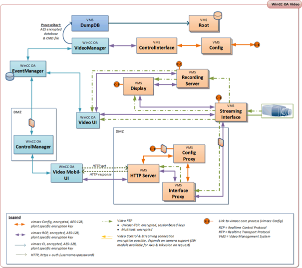
Installed services
WinCC OA Video consists of several components with different responsibilities. It is possible to run these components on one single computer or distributed on several computers in case of large systems. Together these computers form the WinCC OA Video System.
Communication
Because of this distributed architecture the components must communicate with each other to exchange status information or transmit control commands.
Only IP based asynchronous message protocols are used for this communication. Direct interdependencies of the components are prevented which results in a high reliability and scalability of the total system.
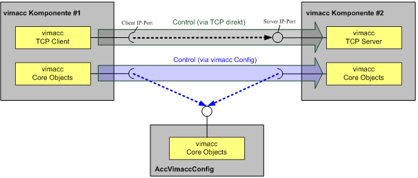
There are two main mechanisms for the communication between components:
-
Communication via AccVimaccConfig: The communication via AccVimaccConfig is a mechanism provided by each component's application framework. The application framework communicates with the AccVimaccConfig component via IP connections and ensures that the AccVimaccConfig is always available as data base for the application. Therefore, each video application can retrieve the relevant control commands from the AccVimaccConfig and deposit control commands and status information. Usually a logic control connection between two components is accomplished via the AccVimaccConfig.
-
Communication via direct TCP/IP connections: In some cases it may be necessary that a component establishes a direct control connection to another component e.g. if particularly low latency is needed. For this reason there is a control channel for each component which is provided by the internal TCP server. This allows a component to establish a connection directly via TCP/IP and transmit control commands to or query status information from another component.
Components
The following operating system services from vimacc are installed during the WinCC OA video installation and run in the background.
- AccVimaccConfig
- AccVimaccConfigProxy
- AccVimaccConfigSlave
- AccVimaccControlInterface
- AccVimaccDongle
- AccVimaccEventManager
- AccVimaccExport
- AccVimaccFtpAlarmReceiver
- AccVimaccHttpServer
- AccVimaccInterface
- AccVimaccInterfaceProxy
- AccVimaccIpAlarmReceiver
- AccVimaccRoot
- Video_grundlagen-05.html#Video_grundlagen-05__AccVimaccRTSPServer
- AccVimaccServer
- AccVimaccSystemMonitor
- AccVimaccCommander
- AccVimaccDisplay
- AccVimaccExportPlayer
- AccVimaccWorkstation
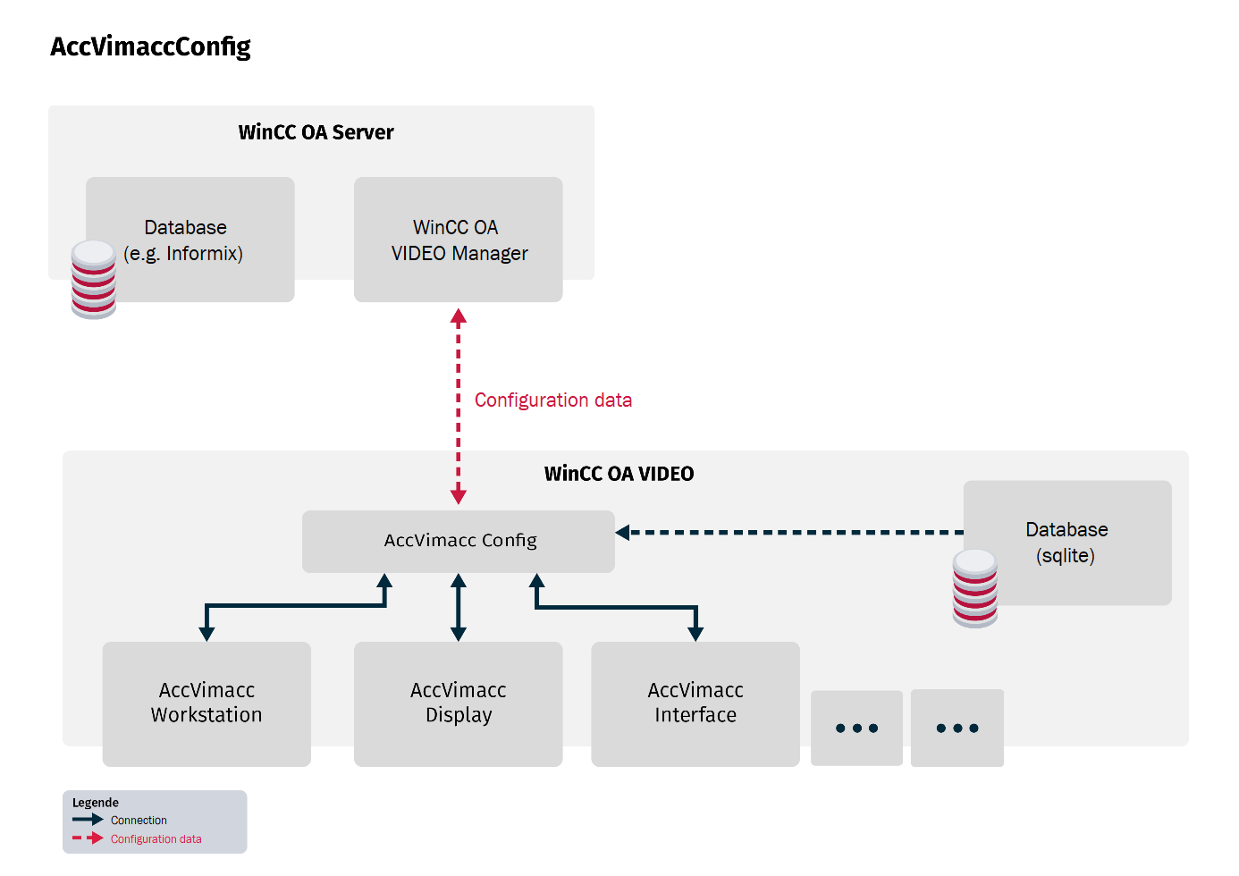
AccVimaccConfig
This service is the central database service for the whole configuration of a WinCC OA video system, its control and its system state. AccVimaccConfig is able to read the static configuration data from a local data base. The input data is provided for all processes of the WinCC OA video system.
All software components of the WinCC OA video system can communicate with this service via TCP/IP in order to query system configuration and system state, to transmit their own state and react to commands.
Not only static configuration data but also dynamic states and control commands are saved in the WinCC OA video system's data pool (the config).
These dynamic information is volatile and is only stored in the memory at runtime. The global configuration data is collected by all WinCC OA video components on a restart. Therefore the AccVimaccConfig is also used as interprocess communication platform for the WinCC OA video processes and implements the WinCC OA video command interface.
Usually AccVimaccConfig runs on a central component of the system, e.g. a WinCC OA server. To increase the system stability it can also run on another host e.g. a redundant WinCC OA server. The redundant host can take over if a component fails. Therefore a failure-free operation is ensured.
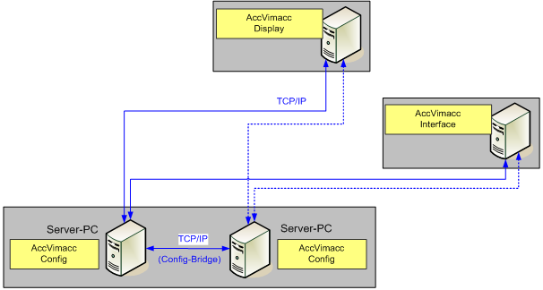
Redundancy
In case of a hot standby system (consisting of two running AccVimaccConfig processes on two different hosts) all software components are communicating with both AccVimaccConfig processes via separated TCP/IP data connections.
In this context the other components are called config clients and the AccVimaccConfig as config server.
Both config servers establish an additional TCP/IP connection (config bridge) among themselves. The state (MASTER or BACKUP) of the processes is defined via this connection.
The state of both config servers is independent from the redundancy of the WinCC OA system.
The state of one config server is MASTER, the state of the other server is BACKUP. Only the MASTER sends state changes to the config clients or responds to their requests. On the contrary the config clients send all requests and state changes to both config servers. Config changes are saved by the MASTER. If the config bridge connection is reestablished the current MASTER sends the entire config information to the BACKUP config server and remains MASTER.
This TCP/IP connection between the redundant servers (the config bridge) is a logic connection. To ensure a correct redundancy switch in case of an error, both servers must not be connected to the network redundantly. Both servers must be connected to the active network component with only one network cable respectively.
Link to WinCC OA server
The connection between a WinCC OA server and WinCC OA video is established via a WinCC OA video manager. At restart of the API manager the manager sends all necessary configuration information to all config servers. After a successful initialization only changes are sent. Messages from the WinCC OA video system are written to the video related data points by the WinCC OA video manager.
AccVimaccConfigProxy
There may be a big communication load on central management servers in complex and multi-branched sites. To ensure a fast reaction time of the servers, the service AccVimaccConfigProxy can be used. This service is automatically installed on every vimacc host and can be enabled to bundle the interprocess communication per host. Thus, concurrent interprocess connections to the central servers are reduced.
In case a site is configured as described in section AccVimaccConfigSlave, the service AccVimaccConfigProxy must not be used for sub nodes.
To enable the bundling of interprocess communication, you have to edit the following config files on the respective vimacc hosts:
AccVimaccConfigProxy.conf
On clients:
[ConfigServer]
Port=9360
ContentUpdateCompressLevel=1

[ConfigClient]
ListenToAnnouncements=false
MulticastInterface=0.0.0.0
Server1=<DNS name server1> 9370
Server2=<DNS name server2> 9370

AccVimaccConfig.conf
On clients:
[ConfigClient]
ListenToAnnouncements=false
MulticastInterface=0.0.0.0
Server1=<DNS-Name des Clients> 9360AccVimaccConfigSlave
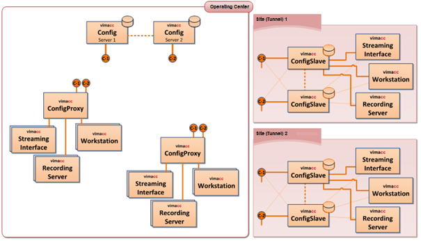
A distributed video system can be divided in different segments (sub nodes). The AccVimaccConfigSlave bundles the interprocess communication necessary for the management and buffers it locally. Therefore, in case of a communication loss (e.g. connection to central management servers is lost) the operability of the respective sub node is still ensured locally. As a result, you can configure recording or streaming nodes with connected vimacc workstations or display servers which will be working independently in case of network problems.
As long as the connection to central management server is established, all WinCC OA video components are available for the sub node.
When the connection to the central management server is lost, the vimacc components for recording and streaming as well as the vimacc workstation for visualization and operation are still available for the sub node.
The use of the AccVimaccConfigSlave component depends on the configuration.
Restart all vimacc processes in order to apply changes to the configuration.
Sub nodes
To enable the bundling of interprocess communication, you have to edit the following config files on the respective vimacc hosts:
AccVimaccConfigSlave.conf
On sub server:
[ConfigProxy]
RCLMode=keep
RCLUseOnlyLocalLicense=false

[ConfigServer]
Port=9365
ClientConnectDelay=0
ContentUpdateCompressLevel=1

[ConfigClient]
ListenToAnnouncements=false
MulticastInterface=0.0.0.0
Server1=<DNS name server1> 9370
Server2=<DNS name server2> 9370
AccVimaccConfig.conf
On sub server & sub client(s) (if present):
[ConfigClient]
ListenToAnnouncements=false
MulticastInterface=0.0.0.0
Server1=<DNS name server1> 9365
Redundant sub node
It is possible to configure a redundant server pair for sub nodes. Following adjustments are necessary:
AccVimaccConfigSlave.conf
On sub server1:
[ConfigProxy]
RCLMode=keep
RCLUseOnlyLocalLicense=false

[ConfigServer]
Port=9365
ClientConnectDelay=0
ContentUpdateCompressLevel=1

[ConfigClient]
ListenToAnnouncements=false
MulticastInterface=0.0.0.0
Server1=<DNS name server1> 9370
Server2=<DNS name server2> 9370

[Bridge]
ServerPort=7001
ServerHost=<DNS name sub-server2>
IAmServer=true -> Definition als TCP-Server
On Sub-Server2:
[ConfigProxy]
RCLMode=keep
RCLUseOnlyLocalLicense=false

[ConfigServer]
Port=9365
ContentUpdateCompressLevel=1

[ConfigClient]
ListenToAnnouncements=false
MulticastInterface=0.0.0.0
Server1=<DNS-Name von Server1> 9370
Server2=<DNS-Name von Server2> 9370

[Bridge]
ServerPort=7001
ServerHost=<DNS-Name von Sub-Server1>
IAmServer=false -> Definition als TCP-Client
AccVimaccConfig.conf
Sub server1, sub server2 & sub client(s) (if present):
[ConfigClient]
ListenToAnnouncements=false
MulticastInterface=0.0.0.0
Server1=<DNS-Name of Sub-Server1> 9365
Server2=<DNS-Name vof Sub-Server2> 9365
Database replication
In case the communication to the central management servers was lost, it is necessary that the configuration database is duplicated to the sub nodes automatically if changed. Otherwise, the sub node might not work with the current state of the configuration database after a restart.
It is recommended to use this functionality in combination with the AccVimaccConfigSlave component (in single and redundant operation). The AccVimaccRoot service which is installed on every vimacc host is also used for this.
In addition to the base configuration (see "sub node" or "redundant sub node") the following adaptions are necessary:
AccVimaccRoot.conf
On sub server1 & sub server2 (if present):
[DatabaseReplication]
Mode=auto
ServerList=<DNS name server1>, <DNS name server2>
AccVimaccConfigSlave.conf
On sub server1 & sub server2 (if present):
[ConfigProxy]
RCLMode=keepWithLocalDB
AccVimaccControlInterface
This component provides the following functions:
-
Interface for a superordinated system to control vimacc
-
Compiling received control commands in vimacc commands
AccVimaccDongle
This component communicates with the license dongles or encryption dongles on each host of a WinCC OA video system.
AccVimaccEventManager
The AccVimaccEventManager enables you to manage and process events and state changes within the video system. It represents a central interface between the components for notifications and event receipts.
The event manager receives and distributes events that are made by different video components. These can, for example, be events like adding or removing a camera, changes in recording state, alert events or other system relevant events.
With the use of the AccVimaccEventManager video components can react to events in a synchronized and effective manner to ensure functionality and performance of the video system.
Because of this the AccVimaccEventManager is an important component for comunnication and coordination in the WinCC OA video system.
AccVimaccExport
AccVimaccExport saves the some parts of the contents which are stored on the streaming servers on the local workstation. It cooperates with the AccVimaccServer component in order to execute this task. This is controlled via data points e.g. the WinCC OA user interface.
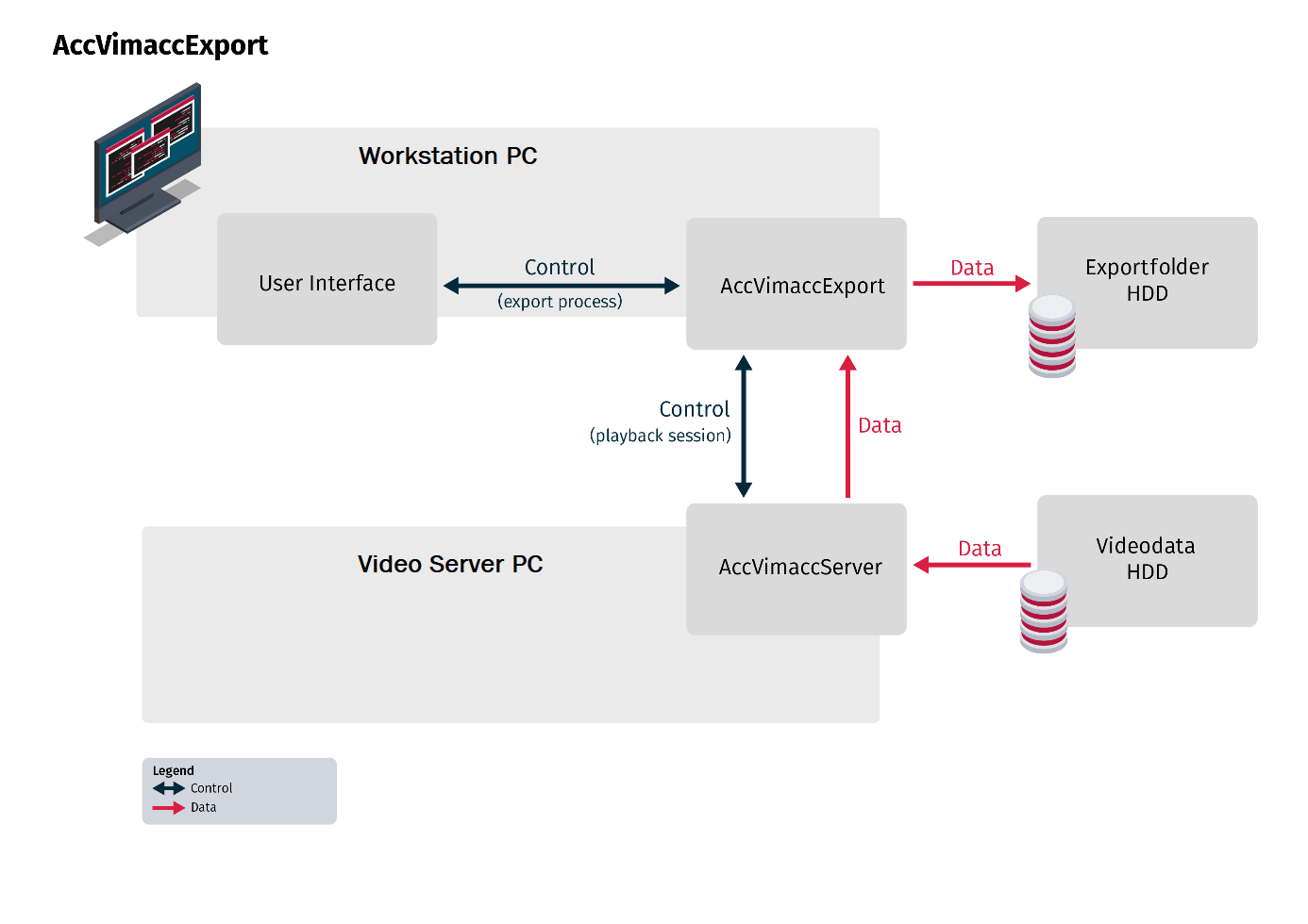
If saved content shall be exported, at first the data is retrieved from the streaming servers and stored on the local hard disks of the computer which initiated the export.
From the controlling component, AccVimaccExport receives the request to export certain parts of the recorded content. AccVimaccExport communicates with the streaming server to call the requested streaming data and store the data on the local computer or a network drive. The current state can always be retrieved by the controlling component via the data points.
The playback of exported streaming data be done via the WinCC OA video component AccVimaccPlayer.
AccVimaccFtpAlarmReceiver
The AccVimaccFtpAlarmReceiver monitors a defined FTP folder and waits to recieve alert files. These alert files contain information on specific events that have occured in the video system, e.g.: movement detection, entry in restricted areas or other types of security alerts
When the AccVimaccFtpAlarmReceiver identifies a new alert file it reads the contained information and sends it to the related component in the video system. This ensures a fast reaction to security relevant events and a targeted handling of alerts.
The AccVimaccFtpAlarmReceiver plays an improtant role in the alert management of the WinCC OA video system and enhances effective monitoring and system security
AccVimaccHttpServer
The HTTP server enables you to access different functionalities and data of the video system via the http protocol.
The AccVimaccHttpServer provides a RESTful-API (Representational State Transfer) through which the external applications or systems can access the video system. The API provides different endpoints and resources over which infomration can be retrieved, actions can be started and settings can be configured.
With this, external applications can, for example, access camera streams, call recordings, query alerts, change configuration settings or send commands to the video system.
The AccVimaccHttpServer enables an easy integration of the video system into other applications or user interfaces as the widesperad HTTP protocol is used to communicate.
With the use of the AccVimaccHttpServers developers can easily access the video system and create user defined applications and integrations to broaden the functionality of the video system and meet special requirements.
AccVimaccInterface
Integrates the different external devices (e.g. video sources) of different manufacturers into one WinCC OA video system. Furthermore it ensures that it is possible to access all these devices within the system via standardized interfaces. AccVimaccInterface is responsible for:
-
Integration of periphery
-
Control of periphery
-
Monitoring of periphery
-
Receiving streaming data
-
Forwarding received data to different receivers
-
Forwarding between IP unicast and IP multicast connections (if necessary)
-
Encryption (if enabled) of received streaming data
-
Transformation of received streaming data (if necessary)
-
Connection to the streaming servers for recording data
Generally the AccVimaccInterface is operated as streaming proxy to cope with the special network topology requirements. This means that streaming data is called only once from the data source even if it is called by several receivers simultaneously.
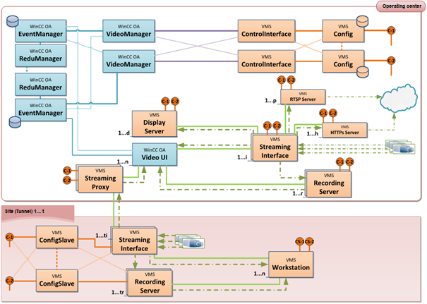
Example of use 1:
This figure shows an example of simultaneously calling streaming data of network cameras via several workstations and one streaming server.
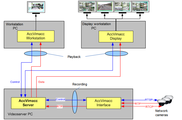
After the data is received it can be requested via the WinCC OA video control connection by the WinCC OA video interface and is transmitted to the receiver per RTP. The AccVimaccInterface monitors the availability of the configured devices. This state is saved in the AccVimaccConfig and other video components can evaluate or display it. AccVimaccInterface can be operated on any computer of the WinCC OA video system. The maximum number of channels which shall be integrated depends on the number of AccVimaccInterfaces instances installed on different computers.
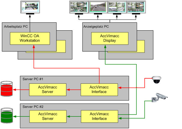
Example of use 2:
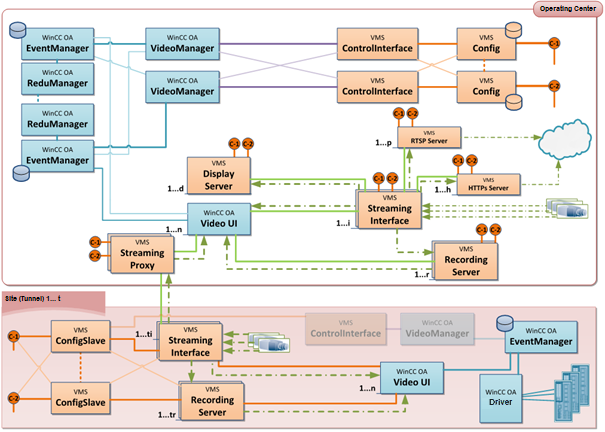
The following picture shows an example of a WinCC OA VIDEO system where several workstations and display monitors are retrieving the data from network cameras. Parallel to that the video data is recorded on a streaming server.
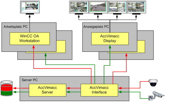
This scenario shows that the video data of a camera is only fetched once from the AccVimaccInterface and forwarded to the receivers. The receivers are the AccVimaccServer, all WinCC OA workstations which are retrieving the image of the camera as well as all instances of AccVimaccWorkstation and AccVimaccDisplay.
Redundant recording
It is possible to configure a WinCC OA system in order to record streaming data redundantly. Therefore continuous recording is ensured even on failure of central components.
There are the following two ways for recording streaming data:
- both WinCC OA video streaming servers are recording all data parallel (complete redundant recording)
- the data sources are evenly distributed to the servers (load balancing)
Complete redundant recording
In this case only one AccVimaccInterface retrieves streaming data of data sources and provides the data to the redundant AccVimaccServer instances for storing. This ensures that both servers can save the same data at the same time in normal operation. The data of the cameras must not be retrieved two times.
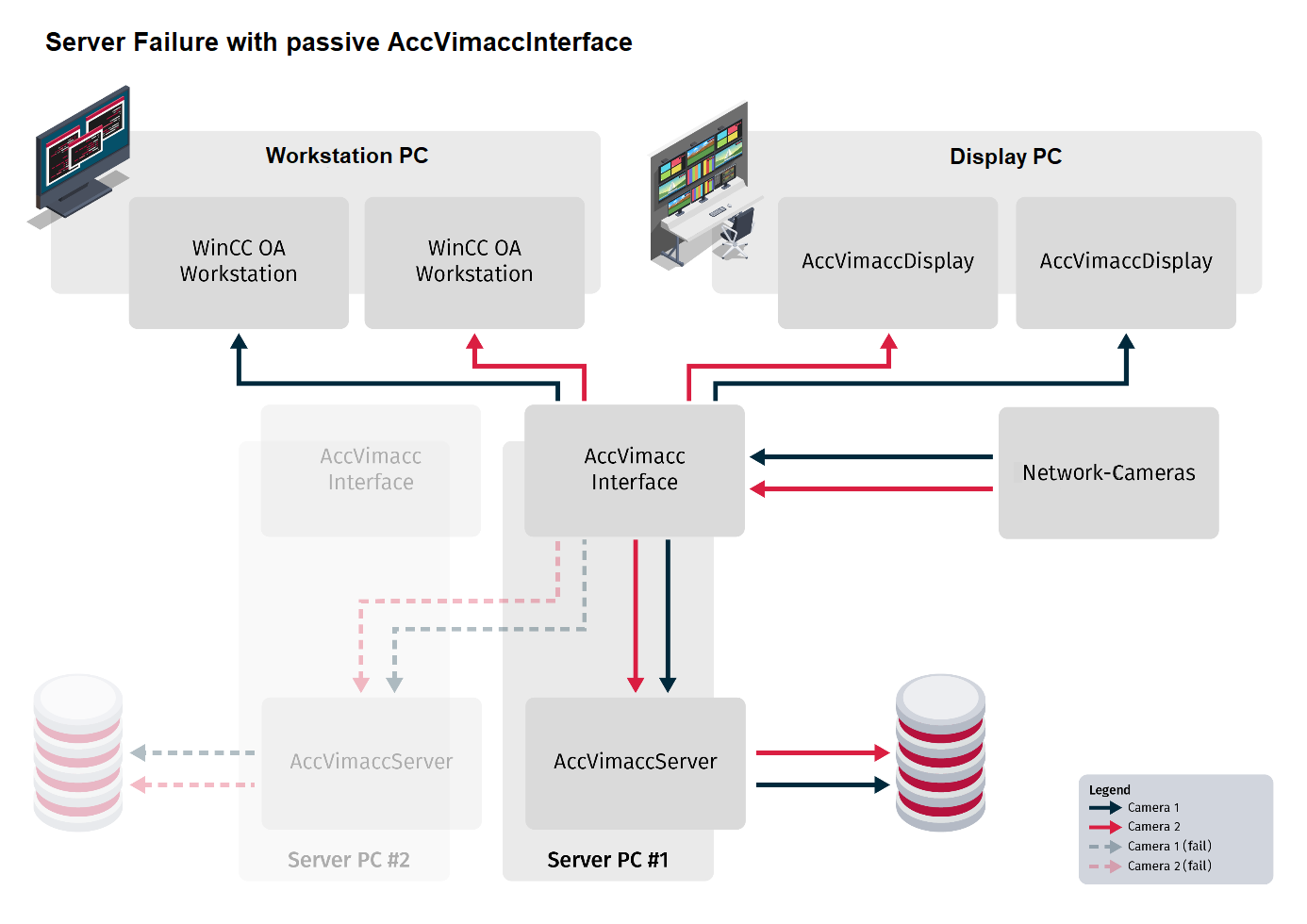
The instances of AccVimaccWorkstation and AccVimaccVimaccDisplay as well as all WinCC OA workstations, which display the camera images, always retrieve the data from the active AccVimaccInterface (server PC #1). The redundant AccVimaccInterface (server PC #2) is on Hot-Standby and waits for a redundancy switch in case of an error.
Therefore there is no recording interruption even if one server fails. The other server can receive and record data, live connections can be established and retrieving already recorded data is also possible. As soon as the failed server is online again the connection to the server is automatically reestablished and both servers will record simultaneously.
In the following figure the server with the passive AccVimaccInterface has crashed.
In this case no redundancy switch is necessary. The instances of AccVimaccWorkstation and AccVimaccDisplay keep retrieving data from the interface of server PC #1.
In the following figure the server with the active AccVimaccInterface has crashed.
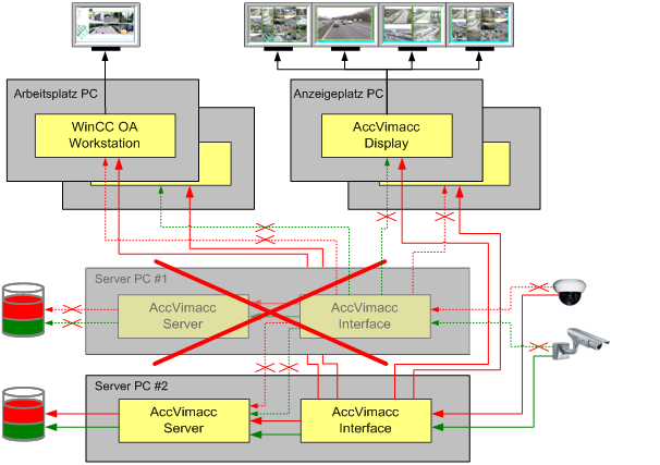
The remaining server recognizes that a redundancy switch is necessary and makes sure that the previously passive interface retrieves the streaming data and establishes the recording connections to the AccVimaccServer. The instances of AccVimaccWorkstation and AccVimaccDisplay as well as all WinCC OA workstations which display the camera image recognize the redundancy switch and retrieve the data from the AccVimaccInterface of server PC #2.
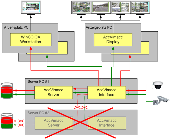
Load balancing
The configuration of the AccVimaccInterface components ensures that only about a half of the connected data sources is assigned to each interface. Therefore each interface retrieves the streaming data of the half of the data sources and transfers it to the linked AccVimaccServer for storing. In normal operation both servers store about the half of the data. The streaming data is only transferred once in the network.
Following figure shows such a WinCC OA system.
The instances of AccVimaccDisplay as well as all WinCC OA workstations which display the camera image retrieve the data from the interface that is assigned to the requested data source.
If a server crashes, WinCC OA video ensures that there is a redundancy switch. The second half of the streaming sources is automatically linked to the remaining AccVimaccInterface. Therefore the data of all cameras is recorded on one server.
The available storage capacity for the ring memory is reduced while only one server is online
Following figure shows the WinCC OA video system with one crashed server.
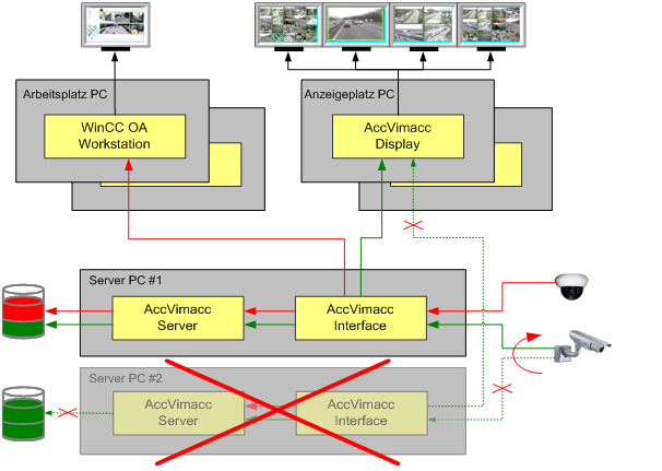
Live connections that were established via the AccVimaccInterface of the crashed server (server PC #2) are automatically established via the second server after the redundancy switch. All new live connections will be established only via the remaining server.
Even if the cameras are now connected to the other server, the data recorded prior to the server failure is only available at the crashed server. Therefore, while the server is down it is not possible to get access to that data.
If a RAID system with an appropriate level (e.g. RAID 5) is used for data storage it is possible to generate redundant information automatically and all data is available even in case of a server failure.
However, the real advantage of this method over complete redundant recording is the ring buffer size. Since only half of the data must be recorded on each server, the ring buffer size can be twice as large.
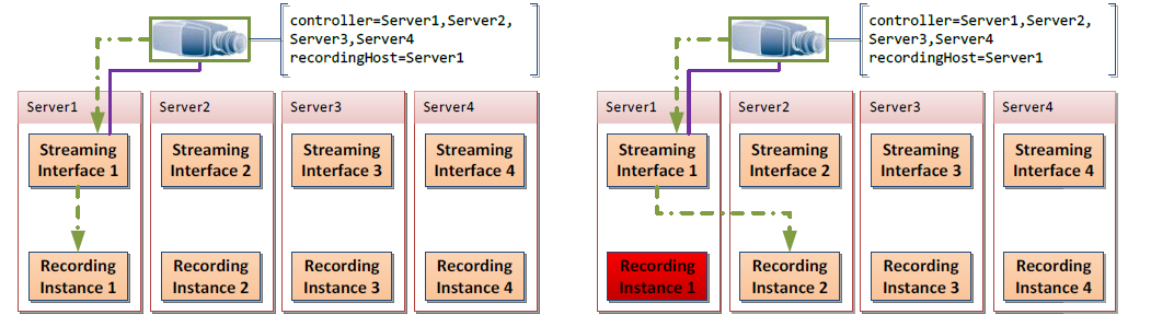
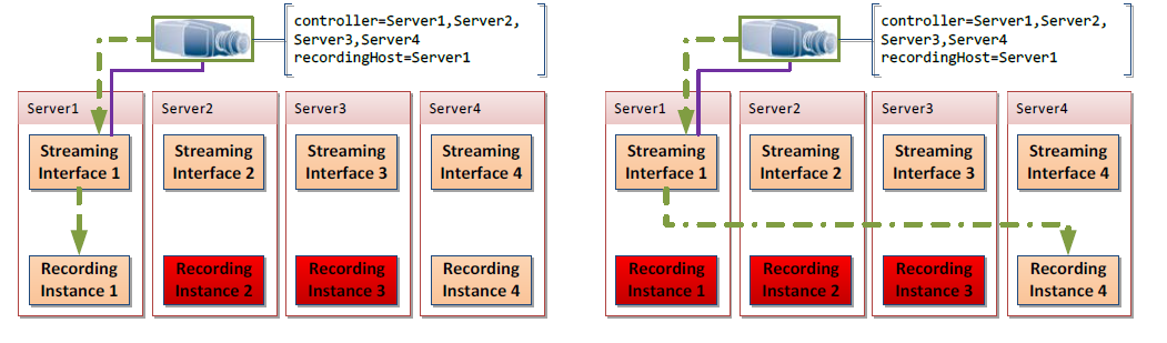
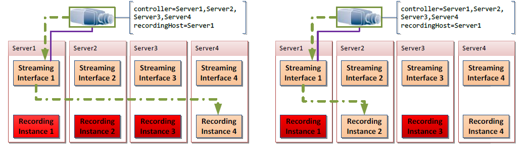
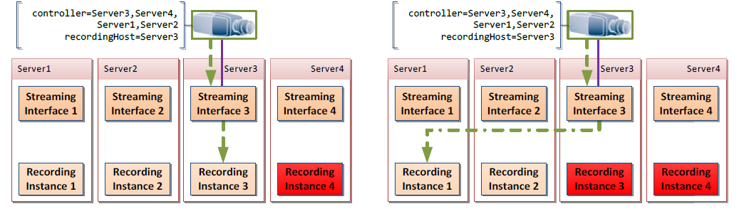
Failover redundancy
You can define four hosts (two Master-Slave pairs) for recording with failover redundancy. The master of the primary host pair is used for recording video data. All other hosts are running in hot-standby. If the master fails, the recording is switched to the slave of the primary host pair. In case that both, master and slave, are down, the recording is switched to the secondary host pair.
The ranking of the failover redundancy is as follows:
Master Primary recording > Slave Primary Recording > Master Secondary Recording > Slave Secondary Recording
As soon as a host is back to normal, the recording will switch from lower ranked hosts to this host.
AccVimaccInterfaceProxy
The main purpose of the interface proxy is to manage the communication between the clients and the servers and to ensure that the requests and data are transmitted correctly.
The AccVimaccInterfaceProxy acts as a central control point for access to the video servers. It receives requests from the video clients, forwards them to the appropriate video server and monitors the exchange of data between the clients and servers.
The AccVimaccInterfaceProxy plays an important role in the scalability and flexibility of the video system. It enables the load to be distributed across several video servers and ensures that requests are processed efficiently and reliably. In addition, the AccVimaccInterfaceProxy also supports the system's security functions, such as authentication and encryption of communication.
AccVimaccIpAlarmReceiver
The AccVimaccIpAlarmReceiver is responsible for receiving and processing IP-based alarm messages. These alarm messages can be generated by various surveillance cameras or other IP-enabled devices.
The alarm receiver continuously monitors the incoming data traffic on the defined IP port and detects incoming alarm messages. As soon as an alarm message is detected, the alarm receiver processes it and forwards it to the relevant components of the video system, e.g. the Video Manager or the Control Manager.
The AccVimaccIpAlarmReceiver plays an important role in the detection and handling of security events in a video surveillance system. It enables the fast and efficient processing of alarm messages in order to trigger corresponding actions such as notifications, recordings or the triggering of events in the WinCC OA environment.
AccVimaccRoot
AccVimaccRoot is the core component on each computer of a WinCC OA video system and is launched on the computer start. This component is responsible for:
- Controlling all WinCC OA video processes on the computer
- Licensing
- Sequential control
Depending on the installed components all additional WinCC OA video processes are enabled and controlled by AccVimaccRoot.
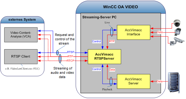
- AccVimaccRTSPServer
- Video streams of a WinCC OA video system can be called via the RTSP interface (Real-Time Streaming Protocol) implemented by this component. Therefore it is possible to call the streaming data via a standardized interface in order to directly display it or pass it to another system for video content analysis.
-
AccVimaccServer
This component implements the streaming server and organizes all recordings within a WinCC OA video system. The recordings are provided to other components for playback. AccVimaccServer is responsible for the following tasks:
- Recording streaming data in central or distributed archives
- Indexing streaming data
- Providing recording modes (ring recording, alarm recording, linear recording)
- Protecting time ranges from deletion
AccVimaccServer records streaming data independent from streaming source and format. The streaming data is taken from one or more AccVimaccInterface instances and is saved on the assigned archives.
When the recorded data is called (e.g. by AccVimaccDisplay or a WinCC OA user interface) it is read from the archive and passed to the requesting process.
Arrangement of media files
AccVimaccServer stores the received streaming data in many files in a defined directory structure. The structure is as follows:
Media root directory (<rootfilepath>)
Context directory (<context>)
Session directory (<session>)
Recording channel directory (<streamname>)
Year directory (<yyyy>)
Month directory(<mm>)
Day directory (<tt>)
Hour directory (<hh>)
Media data is combined in time ranges of equal length. Auf Stundenebene werden die Mediadaten in gleichlange Zeitbereiche zusammengefasst.
The file name of the media data is as follows:
<rootfilepath>\
<context>\
<session>\
<streamname>\
<yyyy>\
<mm>\
<tt>\
<hh>\
<streamname>_<mm>.<audio|video>.<0...N>
The directory names are specified according to the following scheme:
<rootfilepath>: is defined via the user interface
<context>: is defined in the database
<session>: is defined in the database
<streamname>: Consists of the camera data point name and the stream number (1-3), e.g. Camera_00345_2 (Stream 2) or Camera_00345_3 (Stream 3)
<yyyy>\<mm>\<tt>\<hh>\<stream name>_<mm>: is defined by the UTC timestamp of the recorded streaming data.
<audio|video>.<0...N>: Defines the sub streams of a stream with type video and indexing via a digit. The value is defined by the AccVimaccInterface. This allows to record two streams for one video channel with different quality and two different resolutions (e.g. PAL and CIF) which would be stored as *.video.0 and *video.1.
The assignment between streaming data and actual media file is realized via concrete timestamps. These timestamps are stored in the index database. For the media data of a recording channel's sub stream there is always exactly one index database (sqllite3 database) which stores all index information. The file name of the index database is built as follows:
<rootfilepath>\
<context>\
<session>\
<streamname>\
<streamname>.idx\
<yyyymmtt>.idx
Each data block of the stream is stored in the index database with the associated SDP file (Session Description Protocol), the time interval in form of timestamps and the file pointer along with the file index.
Each timestamp is coded in UTC time format and refers to the associated directory via the date. The file index references a one minute long part within the stream. The stream itself is an elementary stream without meta information. If streams are recorded unencrypted the parts can be displayed via standard playback software (e.g. VLC) by renaming the appropriate files (e.g. to *.h264).
AccVimaccSystemMonitor
Monitors the entire system (including all computers, processes, licenses, etc.) to detect the status and provides it in the config.
Process distribution to computers of a video system
It is assumed that separate interface computers are used for the integration of periphery devices (e.g. network cameras). Depending on network and CPU load of the server computers, components of a WinCC OA video interface can also run on the server computers. This depends on the number of streams to be transferred or recorded simultaneously as well as the demanded resolution and frame rate.
Log files
Log files for every service are automatically generated and stored in C:\vimacc\log\<component name>_<hostname>_<date>.log every day.
All time stamps of vimacc services are given in UTC.
The log files are stored for 30 days per default. This time span can be modified via the Logging/Days entry in the conf file of the respective service.
The maximum size of log files can be defined via the following entries in the conf file of each service:
| Entry | Default | Description |
|---|---|---|
| CheckFileSize | 10 | Defines at which size (in Megabyte) the checking algorithm is started. |
| BandwidthCheckInterval | 15 | Time in minutes in which the processed data volume is measured and which must at least elapse till the next check. Note: The elapsed time is determined implicitly when writing the data. Therefore it may happen that more time elapses till the next check, if no or little data is written. |
| MaxLoggingBandwidth | 500 | The maximum amount of new data (in Kilobyte) allowed during the measurement period. |
If the defined size of a log file (e.g. 10 MB) is reached, the configured measurement period (e.g. 15 minutes) is started. The entire written data is added up for the respective time period. After this time has elapsed it is checked whether the processed data exceeds the limit (e.g. 500 KB). If this is the case, an error message is written to the log file and the file is closed.
In addition, the maximum allowed data volume for each day is checked at each write operation. The whole algorithm is performed for each new log file every day.
 Example
[Logging]
CheckFileSize=10
BandwidthCheckInterval=15
MaxLoggingBandwidth=500
The worst case log file size for each service can be calculated as follows:
10 MB + 0,499 MB x 24h x 4 (because the data is measured every 15 minutes) = ca. 58 MB
In case of a default storage time of 30 days this results in a total log file size of 1.8 GB per service.
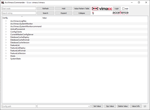
AccVimaccCommander
The AccVimaccCommander is an administration tool to visualize the datapoint layer of the video system in order to obtain more specific infomration about the video system.
AccVimaccDisplay
AccVimaccDisplay is responsible for the video output via multi channel monitors and large screen displays. The component is operated on one host which operates a display unit via one or more graphics adapters. A display unit consists of e.g. monitors, video projections or large-format screens with graphics controllers. Depending on the number of necessary video channels which shall be displayed simultaneously, one or more display workstations are necessary for a WinCC OA video system.
This component does not provide its own user interface and is operated solely by control commands of a WinCC OA video system. Each AccVimaccDisplay is represented by a data point in the WinCC OA system. State information is received at this data point and control commands can be written to it.
AccVimaccDisplay can be completely operated via a WinCC OA user interface. This means that all live and playback connections on video monitors of a video wall including camera control (PTZ) and playback control (play, stop, setposition etc.) can be managed by one user interface.
AccVimaccDisplay increases the latency of the entire transmission path for the video output by not more than 80 milliseconds.
24 video images can be displayed per AccVimaccDisplay. Several AccVimaccDisplay instances can be operated on one computer. The number of simultaneously displayable video streams depends on the number of AccVimaccDisplay instances running on different computers.
Example
A display workstation with high end CPU (e.g. intel core i7) is able to decode and display 64 video channels (live or playback) simultaneously in full resolution (4CIF) and with full frame rate (25 fps).
Two computers with high end CPUs are necessary in order to display e.g. 128 4CIF video channels simultaneously. Since one channel with full HD resolution requires the fivefold performance, 10 computers with high end CPUs are necessary if you want to display 128 full HD video channels simultaneously.
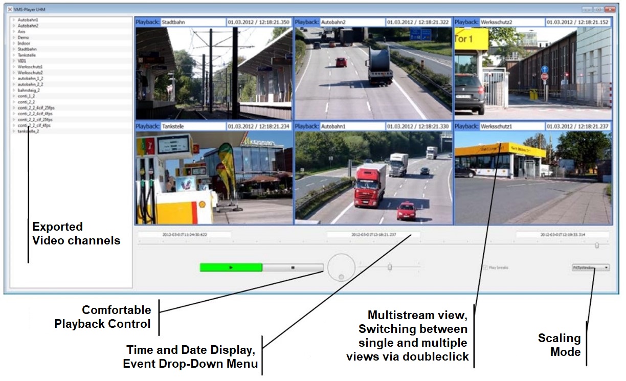
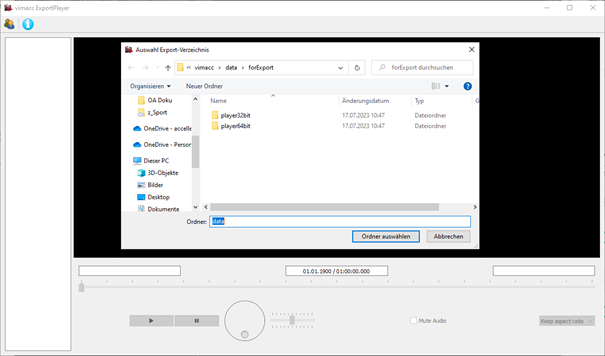
AccVimaccExportPlayer
The Video Export Player of the video managementsystem is a stand-alone-software to show exported Video files. This will be added to the removable media (e.g.: DVD, USB stick, ect.) when exporting video files, which ensures the replay of the files on every desired computer.
The Video Export Player offers the following functions:
- Replay of exported files from a removable media.
- When replaying video files from different video sources, the replay is synchronized.
- Choose cameras from a list.
- Frame accurate navigation in saved video material.
AccVimaccWorkstation
The component AccVimaccWorkstation can generally be used on any computer in the WinCC OA video system and even outside of the video system. For example, it can be added to the removable media on export of recorded streaming data and will then enable replay of this data on any desired computer.

AccVimaccWorkstation provides the following functions:
- Replay of exported streaming data from removable media
- When replaying streaming data from different video sources, the replay is synchronized.
- The maximum amount of simultaneous streams depends on the performance of the work station. A work station computer in the High end CPU class (e.g.: Intel Core i7) can simultaneously decode 64 4CIF video channels (live or playback) in full video source resolution (4CIF) and at full frame rate (25fps).
- Choose cameras from a list.
- Frame accurate navigation in saved video material.


