External events
Depending on the type, cameras or encoder can send messages via their control protocol or a separate IP channel to VIDEO OA. This events are written on the data point element .object.device.alarm.
Currently only binary events are supported.
The events are passed as key value pair with a keyword and a value. The keyword depends on the device type. In case of some device types it is possible to define the keyword during the device configuration.
For example the motion alarm of a camera is passed as MOTION=1, the state of the digital input is passed as input1=1 or input1=0. If an event is reported as CAME or CAME and WENT depends on the message and the device type. Only the last message is stored on the data point element .object.device.alarm. Therefore, the current state of events that are reported as as CAME and WENT must be queried on the device during a restart.
Configuration
The device events can be assigned to any data point element. This is possible via the menu point external event opened by a right mouse click on cameras or encoders.
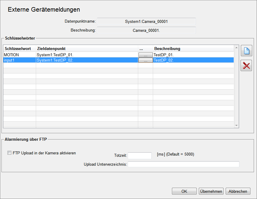
Events with the keyword MOTION are assigned to the data point element TestDP_01, events with keyword input are assigned to TestDP_02.
 adds a new row
to the table. A new keyword can be entered in this row. The ... button opens a data
point selection dialog in order to select the target data point. The column Description
automatically shows the description text of the target data point.
adds a new row
to the table. A new keyword can be entered in this row. The ... button opens a data
point selection dialog in order to select the target data point. The column Description
automatically shows the description text of the target data point.
 deletes the
selected row.
deletes the
selected row.
If the data point element .object.device.alarm contains the string input=1, the data point element TestDP_02 is set to 1 by a dpSet. If the data point element contains the string input=0, the data point element TestDP_02 is set to 0. There is no old/new comparison.
Overview of external device events
The following overview panel can be opened via the external device events button in the system management. All device events in the system are displayed in this overview. The following information is displayed:
-
Target data point
-
Camera or encoder data point
-
Description
-
Keyword
-
Active - shows whether the alert handling of the target data point is active or not
-
Alert class of the target data point
Errors detected in the configuration are highlighted in color and further explained in the text field below. The list is updated online.
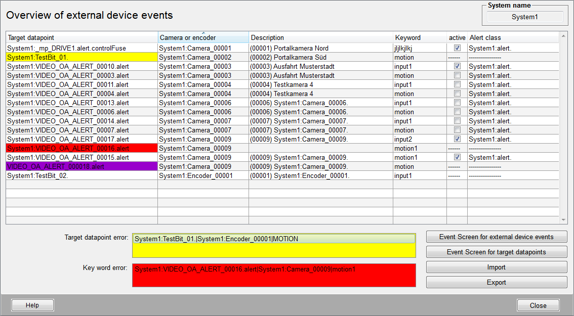
There are three different configuration errors that can be detected:
-
Error on target data point selection
This error is highlighted in yellow and indicates that a target data point is assigned several times. The first found assignment is shown in the table and the target data point is highlighted in yellow. All other assignments are shown under the table. The internal logic always writes the last received event on the data point element.
-
Error on keyword selection
This error is highlighted in red and indicates that a keyword is used for a device twice. Since only one link to the keyword is processed, this configuration results in a malfunction. This error is prevented in the configuration panel of the device. Therefore it can only occur due to a erroneous import of the configuration.
-
Target data point does not exist
This error is highlighted in magenta and indicates that the configured target data point does not exist.
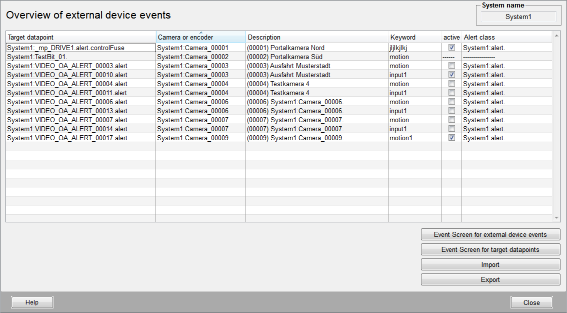
If no configuration error is found no lines are colored and the text fields are not displayed.
The four buttons in the panel provides the following functions:
Event Screen for external device events
The following panel is opened via the button "Event Screen for external device events". The events received on data point element *.object.device.alarm can be traced online via this panel. Historical analysis is not possible with this panel.
 - starts the table update
 - stops the table update
 - deletes the table
The update status is shown to the left of the buttons.
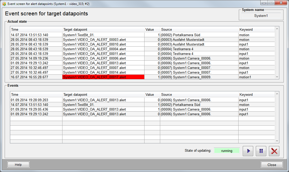
Event Screen for target data points
The following panel is opened via the button Event Screen for target data points.
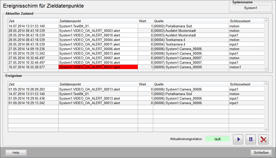
The current state of all configured target data point elements is shown in the "Actual state" table. The following information is displayed:
-
Time of the last change
-
Target data point element and current alert color
-
Current value
-
Source of the device event
-
Keyword
Changes on the target data points can be traced online in the "Events" table below. Historical analysis is not possible. The following information is displayed:
-
Time of the change
-
Target data point element
-
Current value
-
Source of the device event
-
Keyword
- starts the update of the "Events"
table
- stops the update of the "Events"
table
- Deletes the content of the "Events"
table
The update status is shown to the left of the buttons.
Import
The import button opens the following dialog which is used for importing device events.
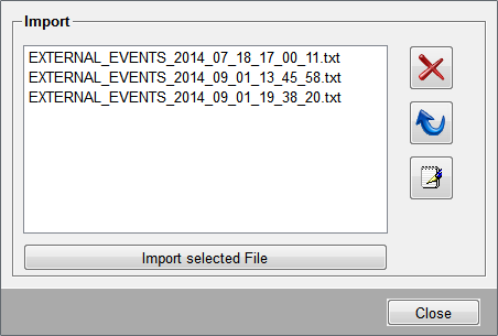
All files in the /data folder which correspond the naming convention EXTERNAL_EVENTS_*.txt are provided for the import. The file must be selected in the list. Then the import can be started by the button. The import is performed without any consistency check.
- deletes the selected file
 - updates the file overview
 - opens an editor to modify the
selected file
- opens an editor to modify the
selected file
Export
This button exports the configuration of external device events to a file. The file is stored in the /data folder of the project. The file name is automatically generated as follows:
EXTERNAL_EVENTS_<year>_<month>_<day>_<hour>_<minute>_<second>.txt
(e.g EXTERNAL_EVENTS_2014_09_01_19_38_20.txt)
The file is a text file whose entries are separated by tabulators. The first row is meant for commentating and is ignored by an import. Each further row contains the configuration for a device.
The first column always contains the device name. After that there are two columns for each configuration respectively. The first of the two columns contains the target data point, the second one the corresponding keyword.
Column 1 = Device name
Column 2, 4, 6,... = Target data point
Column 3, 5, 7,... = Keyword


