Modbus/TCP Driver - Periphery Address Panel
The configuration panel of a peripheral address for the Modbus/TCP driver.
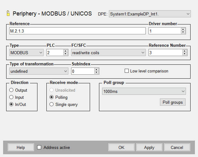
You can enter the address directly in the Reference text field or create it with the spin buttons.
- type
-
- MODBUS
- UNICOS
- PLC
- Number of PLC that has been set on the internal data point of the type _Mod_Plc during configuration.
- FC/SFC
- The possible function codes. All combinations of function codes, modes and
addresses are not possible. The used function code depends on the PLC in the
slave mode of the WinCC OA driver. The allowed values of the
FC/SFC field are:
Output Input Polling Input Spontaneous MODBUS 5 write coil
6 write single register
15 force multiple coils
16 write multiple registers
23 atomic read/write
1 read coils
2 read input discrete
3 read multiple register
4 read input register
7 read exception status
24 read FIFO queue
5 write coil
6 write single
15 force multiple coils
16 write multiple coils
23 atomic read/write
UNICOS not applicably not applicably 1 status
17 events32 (32 bit event frame)
18 events (16 bit event frame)
Note:The function code 23 is only used for atomic write/read operation, which means that a read operation is always combined with a write operation. Therefore, Polling or Single Query mode are not supported by these addresses.
The receive mode is always "Unsolicited", because the reading is an implicit consequence of the write.
Further information on the function code 23 (0x17) can be found in the chapter FC23
- Reference Number
- The reference number indicates the address within the PLC. It is important to
note that the reference number is dependent on the function code. The reference
number is an address with 16 bit word (a 2 byte integer without sign) for
register based function codes and a bit number (a 2 byte integer without sign)
for bit based function codes.
Note:Assure that the used function codes are compatible with the data types! The driver only checks the compatibility of the function code with the transformation type.Note:By spontaneous input mode and function code FC 15 (force multiple coils) only use reference numbers divisible by 16 (an error message is shown when using numbers not divisible by 16) . The sub index can lie between 0 and 1919. For all other cases this modulo 16 limitation does not exist.
- Type of transformation
-
Choose the transformation type of the Modbus driver from the combo box (see Reference tables). The subindices for the Modbus are dependent on the transformation type. If the current value is bigger than the upper boundary when changing the type of transformation the subindex is set to the new maximum value.
The Modbus driver now supports the access to bit groups in a Modbus register. This can be used for the realization of multi-state variables, which contain a configured number of bits. These bits must be consecutive in the register and must not exceed the register boundary. To configure such an address the transformation type "boolean" must be selected.
The "Subindex" defines the offset inside the register and the "Bits" field allows to configure the number of bits.
- Specialities with the transformation type "blob" and "string"
- When reading a Modbus register with the transformation type
"string" or "blob", the number of bytes to be read can be set
via an optional parameter
[:<number of
                                        bytes>]
in the address reference. E.g.: the address reference>M. 1. 3. 10:100reads 100 bytes starting with the addressM. 1. 3. 10. By default, the driver does always read the maximum data length of 240 bytes.When writing a blob or string, by default only the number of bytes according to the blob or string length, inclusive the zero at the end, is written. For write operations the optional parameter
[:<number of bytes>]can also be used in the address reference. E.g.: the address referenceM.1.3.10:20writes a maximum of 20 bytes starting at the addressM.1.3.10. In this example, if a blob or string with a data length > 20 bytes is written, then the driver issues an error message in the log.
- Subindex
-
The subindex of the Modbus is dependent on the transformation type. The restriction results from the maximum data length of 240 bytes in a Modbus frame as well as from the function codes:
Transformation type Maximum subindex Possible function code boolean 1919 FC 3 (read multiple registers)
FC 4 (read input registers)
FC 16 (write multiple registers)
FC 24 (read FIFO queue)
char 239 int16 119 uint16 119 int32 59 uint32 59 int64 29 uint64 29 byte 59 float 59 double 29 boolean 1919 FC 1 (read coils)
FC 2 (read input discretes)
FC 15 (force multiple coils)
boolean as byte 0 FC 5 (write coil) boolean 15 FC 6 (write single register) char 3 int16 0 uint16 0 boolean 7 FC 7 (read exception status) char 0 MOD10 Size 2 0 FC 3 (read multiple registers)
FC 4 (read input registers)
FC 16 (write multiple registers )
MOD10 Size 3 0 MOD10 Size 4 0 - Low level comparison
- You can choose this option only when the transfer direction is set to Input. If the option is chosen the data is only sent in case of changes. The comparison is based on the raw data without conversion.
- Direction
- Define if you want to send values of a data point element to the command direction (output) or to the alert direction (input) or both directions (in/out) via the Direction radio buttons.
- Receive mode
- There are following receive modes for the input:
- Unsolicited
- Polling
- Single query
- Poll group
-
Choose already existing poll groups. If there are no poll groups available you have to create them with the specific polling parameters in a separate panel. The panel is opened by clicking on the Poll groups... button (see Poll groups for more information on poll groups and polling parameters).
- Address active
- TheAddress active check box is chosen. The address is
used by the driver (seeReference
tables). An inactive address exists and the attributes can be set and
queried but the driver does not use them. This means that no values can be sent
to remote system or received from the remote system for this data point.
Note:The Modbus driver will perform a general query when establishing a connection. This behavior can be changed using the config entry [mod] autoGQ.


