UNICOS
The driver can be used for Modbus/TCP or UNICOS (recommended) at the same time. The master side of the UNICOS is identical to the standard Modbus protocol.
The driver decides whether to use a UNICOS frame or a Modbus frame for the slave by observing the reference number of the Modbus frame. The reference number for a UNICOS frame is 0xFFFF. This means that the reference number 0xFFFF may not appear in the Standard Modbus. The reference number can be set via a config entry - see also Modbus/TCP driver details.
The information for the UNICOS protocol is split into:
-
Binary status
-
Analog status
-
Events
-
Requests
Frames
There is an additional subfunction code in the Modbus frame for UNICOS. The code is transferred in the first byte of the Modbus frame data. The value is 0x01 (1) for binary and analog status, 0x12 (18) for events and 0x11 (19) for 32 bit events. There is no difference between binary and analog status so which data is received is specified by defining a DPE type for the respective address. The maximum size of an UNICOS frame is 253 bytes.
-
Event Report Frame
In case of an event frame the event offset (the reference number) must be used to assign the value to a specific DPE.
-
Request Frame
The Request Frame is a standard Modbus frame and consists of one or more 16 bit words.
The time stamp in a UNICOS frame is treated like UTC time (Universal Time Coordinated)!
Peripheral address
The address is similar to that of the Modbus. The only difference is that the subfunction code replaces the function code for the input data. In order to interpret the address correctly UNICOS has to be chosen when the type is specified.
![]() Example
Example
U.4.1.100
U stands for the UNICOS address type, 4 for PLC 4, 1 (0x01) for a binary or analog status message and 100 for the bit number or analog status address (offset, reference number).
Master and Slave
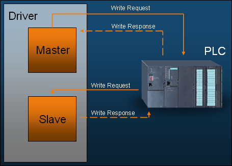
The WinCC OA driver must be a master and a slave at the same time for the UNICOS protocol:
-
The status data and events are only sent spontaneous, no polling is required. For this data the driver has to be the Modbus slave (TCP server).
-
Driver sends the requests as a Modbus master (TCP client).
UNICOS summarizes binary and analog data in a table. A table contains 96 16-bit words. If one element in a table changes the whole table is sent. The tables are sent every 50 milliseconds, tops.
The event table contains the changes of the bit status in a time resolution of 10 milliseconds. The table is sent either when it is full or after 2 seconds.
Though the data in the events correspond to the binary status data, separate data points must be used because the time stamp of the event data may be older than the earlier sent regular bit status.
The data flow for the UNICOS protocol is shown in the following figure. As you can see only write requests are used for Modbus/TCP.
The internal alive mechanism of the driver is described with the entry aliveTimeout in the config file (see Modbus/TCP driver details).
Redundancy concept
The following figure shows the redundancy concept. Both the control system (WinCC OA) and the PLC are redundant:
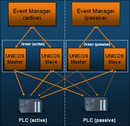
The data flow between the driver and the PLCs is indicated only for the request direction (see figure above).
The thin arrow lines represent the communication channels in case of a redundancy switch-over (they are not used in an actual active/passive state).
The active driver sends the requests to both the active and the passive PLC. Both the active and the passive PLC must respond to the request. The status information and event reports to both WinCC OA drivers are however only sent by the active PLC.
It is important that no read requests are sent by the driver because the driver would have to filter the responses of the redundant units. Since only the active PLC sends data, the interfaces can handle the spontaneous data in the driver equally. The driver does not need to know which PLC is redundant and which active.


