Modbus/TCP Driver - Details
This chapter is intended for advanced WinCC OA users. It describes in detail the function codes, config entries and debug possibilities.
Function codes
The following table contains the possible function codes as well as a short description. If WinCC OA operates as a Slave the function code depends on the used PLC.
| Function code | Code | Description |
|---|---|---|
| read coils | 1 | Reads the ON/OFF status of a discrete output. |
| read input discretes | 2 | Reads the ON/OFF status of a discrete input. |
| read multiple registers | 3 | Reads the binary content of Holding Register. |
| read input registers | 4 | Reads the binary content of input Register. |
| write coil | 5 | Sets a single coil to either ON or OFF |
| write single register | 6 | Writes a value in a holding register. |
| read exception status | 7 | Reads the content of eight exception status coils. |
| force multiple coils | 15 | Sets each coil in a sequence of coils to either ON or OFF. |
| write multiple registers | 16 | Writes values in multiple holding registers. |
| atomic read/write | 23 | Allows to execute an atomic write/read operation. |
| read FIFO queue | 24 | Reads the contents of FIFO queue registers |
- FC23
-
The Modbus function code 23 (0x17) gives the opportunity to execute an atomic write/read operation. It is defined in the Modbus specification that the write operation must be executed before the read operation in the device.
This allows to implement a command with returned data in the device, because the operation is done in atomic way.
If the function code is specified with one address, (This is the usual case like all other addresses look like.) the writing to this address executes also a reading of the same address. The corresponding input value can be received on the same DPE (I/O) address or on another DPE with the same address in Input Unsolicited mode.
It is also possible to specify a different read address by adding an optional address part
/<read address>[:<length>]to the address reference, e.g. the addressM.1.23.5/15will write address 5 and read address 15.Note:The read value can be only received on a separate input address specifying the read address of the telegram. For the example above this would be the addressM.1.23.15.To give another example, where the user want to write a blob of 10 bytes starting from address 20 and read a blob of 30 bytes from address 100. So you have to configure one Output address
M.<plc number>.23.20:10/100:30and one Input address in unsolicited modeM.<plc number>.23.100:30.
Debug levels
There are several command line debug options for the Modbus/TCP driver. These options are used to find errors during the driver operation. Information on further options can be queried with -helpdbg (see also manager options).
| Debug level | Description |
|---|---|
| -dbg 2 | Informs about the driver operation in detail. It is recommended to set this option only when the driver load is low in order to not affect the time performance of the driver. |
| -dbg 25 | If you suspect that a polling request has lost its message, this option can be used. The option activates the corresponding error messages and displays these messages in the Log Viewer. These error messages are normally deactivated because they are not critical for a polling request. In addition to the lost polling tasks this debug level can be used for displaying warnings when data that does not belong to any configured address arrives. The warnings are filtered via debug level since the logging would be overfilled with logging messages which in most cases are not necessary for the user. |
| -dbg 26 | Displays the amount of frames in the Modbus queue. |
| -dbg 27 | Displays the transaction IDs of running Modbus frames. The option can be used to check the amount of unconfirmed requests. |
| -dbg 9 | Can be used to obtain information of the driver cycle time. |
| -dbg 10 | With this debug level the time stamp of the UNICOS Event frames is shown in the Log Viewer in order to find errors related to time stamps in UNICOS Event frame generation. |
| -report ALL | Activate this debug level at runtime to display the poll groups and poll blocks. |
Transformations
A transformation converts hardware data into a WinCC OA format. The following table contains information of transformations and compatibility with the function codes. The driver controls if a data type and code are compatible. If they are incompatible an error message is displayed.
| Required data type | Trafo | Subindex (Array) Support |
Item size [byte] |
Elements in an item | WinCC OA element type | FC for Write Request | FC for Read Request |
|---|---|---|---|---|---|---|---|
| bit | boolean | ✔ | 1 | 8 | bool | 15 | 1, 2 |
| bit | boolean | ✔ | 2 | 16 | bool | 6, 16 | 3, 4, 7, 24 |
| bit | boolean as byte | ❌ | 1 | 1 | bool | 5 | none |
| byte | byte | ✔ | 2 | 2 | char | 6, 16 | 3, 4, 7, 24 |
| word | int16 | ✔ | 2 | 1 | int | 6, 16 | 3, 4, 24 |
| unsigned word | uint16 | ✔ | 2 | 1 | unsigned | 6, 16 | 3, 4, 24 |
| dword | int32 | ✔ | 4 | 1 | int | 16 | 3, 4, 24 |
| unsigned dword | uint32 | ✔ | 4 | 1 | unsigned | 16 | 3, 4, 24 |
| qword | int64 | ✔ | 8 | 1 | long | 16 | 3, 4, 24 |
| unsigned qword | uint64 | ✔ | 8 | 1 | ulong | 16 | 3, 4, 24 |
| float | float | ✔ | 4 | 1 | float | 16 | 3, 4, 24 |
| double | double | ✔ | 8 | 1 | float | 16 | 3, 4, 24 |
| string | string | ❌ | max. 240 | 1 | string | 16 | 3, 4, 24 |
| blob | blob | ❌ | max. 240 | 1 | blob | 16 | 3, 4, 24 |
Writing bits of Holding Registers
If only several bits of the register shall be written, the unused bits are automatically set to 0, since the driver can only write the whole register. To avoid this, you have to configure all 16 bits in WinCC OA, read them and set the bits accordingly. However, the driver does not perform a read before write. This function must be implemented by the user.
Reading bits from Holding or Input Registers
There are the following methods if you want to read bits from Holding Registers and map them to single data point elements.
- Method 1
-
Create a new data point type with a struct node of type bool. Every node you add to this struct is automatically a bool element. You have to add 16 nodes to map all 16 bits of the Holding Register.
Create a data point of this type and add an _address config to the struct node. Configure the register to read (register 10 in this example) and set function code 3 (read multiple registers) and transformation type boolean.
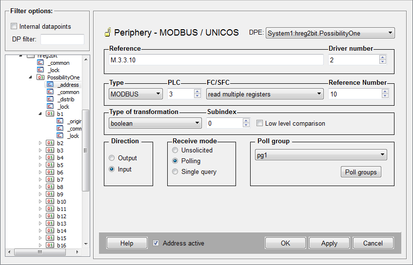
If you read the register the 16bit word is mapped to the 16 bool elements (b1 - b16).
- Method 2
-
Create 16 data points of type bool and add an _address config to each data point. Configure the register to read (register 12 in this example) and set function code 3 (read multiple registers) and transformation type boolean. Define the respective sub index for each element (DPE1 = sub index 0, DPE 2 = sub index 1, ...) to map the bits to the elements.
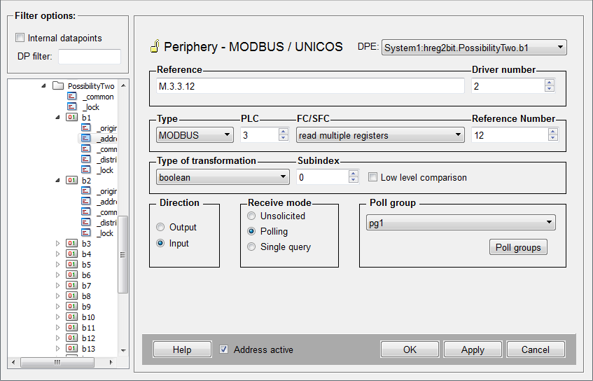
If you configure Polling for the _address configs, note that you have to use the same poll group for every element since a register is always read as a whole. Otherwise the word is read multiple times.
Error codes
The table in this chapter describes the error codes of the PLC configuration panel (see Configuration panel of the Modbus/TCP driver).
| Error number | Description |
|---|---|
| 0 | no error |
| 1 | Master connection to PLC disconnected, no attempt of reconnection |
| 2 | Master connection to PLC disconnected, attempt of reconnection |
| 3 | Error in the slave connection |
| 4 | Peer closed the slave connection |
| 5 | Overflow of the Modbus queue. |
| 6 | Error in frame decoding |
| Error number | Description |
|---|---|
| 101 | Illegal function |
| 102 | Illegal data address |
| 103 | Illegal data value |
| 104 | Illegal response length |
| 105 | Acknowledge |
| 106 | Slave device busy |
| 107 | Negative acknowledgement |
| 108 | Memory parity error |
| 110 | Gateway path unavailable |
| 111 | Response from Gateway target device failed |
Error Messages
The following table describes the error messages of the Modbus/TCP driver.
| Class | Error message | Description |
|---|---|---|
| ModConnection | Too many PLCs on one gateway | Too many PLCs with the same IP address. |
| ModHWMapper | Illegal transformation type for ... | An invalid transformation type was defined for a peripheral address config. |
| ModHWMapper | Subindex + transformation type exceeds max. data length ... | The subindex transformation and function code exceed max. data length. |
| ModHWMapper | Wrong Output function code for: ... | The function code is not allowed for an output DPE: |
| ModHWMapper | Wrong input spontaneous function code for: ... | The function code is not allowed for a spontaneous input DPE |
| ModHWMapper | Ref. number not modulo 16 for spontaneous mode and FC15 for: ... | The reference number for this combination has to be modulo 16. |
| ModHWMapper | Wrong input polling/squery function code for: ... | The function code is not allowed for polling or Single Query output DPE. |
| ModHWMapper | Wrong mode for: ... | Wrong input type for peripheral address config. |
| ModHWMapper | Transformation/FC incompatibility for: ... | Illegal combination of function code and transformation type. |
| ModHWMapper | UNICOS SFC != 0 and FC != 16 for: ... | UNICOS uses only the function code 16. |
| ModMasterConnection | Socket error during send | Error in socket during the data transmission. |
| ModMasterConnection | Cannot establish connection to server | The master cannot establish a connection to PLC either because of wrong host name/port number or because of a network problem. |
| ModMasterConnection | Peer has closed connection | The PLC closed the connection. |
| ModMasterConnection | Connection to ... marked as dead | The connection was assigned as "dead". No connection retries. |
| ModModbus | Error during reception of ASCII frame | No valid ASCII frame received. |
| ModModbus | No PLC for unit address: ... | No PLC with the received Unit address for this connection defined. |
| ModModbus | Invalid Request Size field | A Modbus frame without a valid Request size was received. The frame identification is not synchronized in this case. The connection will be closed and opened again in order to debug the error. |
| ModModbus | Error too many invalid frames | Too many wrong frames were received. This is a sequence error and occurs as a result of earlier errors. This causes a reopening of the connection. |
| ModModbusMaster | No host/unit address defined for PLC number: ... | There is no Host/Unit address defined for the PLC number. This error is caused if no internal DP (_Mod_Plc) was created for this PLC number. |
| ModModbusMaster | Unknown function code specified in Peripheral Address | Invalid function code contained in the PA. |
| ModModbusMaster | Missing some responses to outstanding requests | Some answers to outstanding requests are missing. |
| ModModbusMaster | Receiving Modbus frame without request | Receipt of an answer without sending a request. If too many errors of such kind occur, the connection is closed and reopened. |
| ModModbusMaster | Wrong unit address received: UA= ... | Receipt of a wrong Unit address for an outstanding request. If too many errors of such kind occur, the connection is closed and reopened. |
| ModModbusMaster | Exception code received: EC= ... | An error from PLC. PLC could not handle the request. The meaning of the exception code can be taken from the error codes table. |
| ModModbusMaster | Wrong response to output FC | Wrong response to a particular request. If too many errors of such kind occur, the connection is closed and reopened. |
| ModModbusMaster | Wrong response to read registers request | Wrong response to a particular request. If too many errors of such kind occur, the connection is closed and reopened. |
| ModModbusMaster | Wrong response to read discretes request | Wrong response to a particular request. If too many errors of such kind occur, the connection is closed and reopened. |
| ModModbusMaster | Wrong response to read exception status request | Wrong response to a particular request. If too many errors of such kind occur, the connection is closed and reopened. |
| ModModbusMaster | Wrong response to read FIFO request | Wrong response to a particular request. If too many errors of such kind occur, the connection is closed and reopened. |
| ModModbusSlave | Slave received unknown function code | The slave received an unsupported or invalid Modbus function code. |
| ModModbusSlave | Invalid number of events in UNICOS Event Report | An invalid number of Event field in UNICOS Event Report Frame. |
| ModModbusSlave | UNICOS Slave received unknown subfunction code | The slave received an unsupported or invalid function code. |
| ModOutputQueue | Maximum requests in queue, request discarded | Overflow of Modbus queue occurs. |
| ModOutputQueue | Discarding polling requests (Msg. every 100) | The same polling request is already in the queue, the current is discarded. This warning appears only when the driver starts with -dbg 25. |
| ModOutputQueue | Timeout appears for last sent request | A Modbus transaction timeout for a request occurred. |
| ModPlc | Error during setting of PLC data | An error occurred during setting the PLC data of an internal data point. Use -dbg 2 for further information (DP Identifier) on this error. |
| ModPrLayer | Cannot start Server | The driver can not create a server socket. The port number is probably already in use. |
| ModRsrce | Unknown keyword in config file | The config file contains an unknown entry. |
| ModSlaveConnection | Socket error during send | An error occurred during the data transmission via the socket. |


