Sample IEC driver
This chapter provides step-by-step instructions for establishing communication between IEC drivers. The example sends data between two WinCC OA projects on one computer. In real operation, WinCC OA usually operates as a master (TCP client) and a remote-control station supplies the data as slave (TCP server).
The config files are designed to allow you to establish communication between IEC 104 drivers and IEC 101 drivers by changing the comment marks.
Establishing communication
- Specify the config file entries (see IEC driver config file).
Details to the entries in the config file you will find in the chapter Possible IEC driver config entries.
IEC101 master system config file (Unbalanced Mode)
#IEC CONNECTION for Master:
#Section for iec101:
[iec_1]
device_101 = "Com1" "V24" "com1;9600,e,8,1"
balanced_101 = "No"
sizeof_LA_101 = 1
master_101 = "Yes"
#Section for iec104:
# None
IEC101 slave system config file; WinCC OA is the slave in this case! (Unbalanced Mode)
#IEC CONNECTION for Slave:
#Section for iec101:
[iec_1]
connection_101 = "WinCC OA" "Com2" 1
device_101 = "Com2" "V24" "com2;9600,e,8,1"
balanced_101 = "No"
sizeof_LA_101 = 1
master_101 = "No"
#Section for iec104:
#[iec_1]
#tcpServerPort = 2404
In Unbalanced Mode the config entry "sizeof_LA_101" must exist and must have a value unequal 0!
Config file for Balanced Mode
[iec_1]
device_101 = "Com1" "V24" "com1;9600,e,8,1"
balanced_101 = "Yes"
#Station A/0 or B/1 is defined with following entry.
#Must fit to remote station. If remote station is A, driver must be B.
station_101 = 1-
Define the connections (_IecConnection) using the appropriate panels (see Panel for connections). The client "IEC_TARGET" data point gets the following connections:
Figure 1. Panel with connections 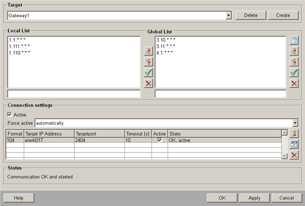
-
Enter the connections as above (see also Connection settings).
Figure 2. For IEC 104: 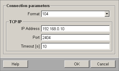
Figure 3. For IEC 101: 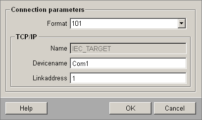
-
Afterwards enter the same connections for the "WinCC_OA" server data point with the panel for connections.
Figure 4. For IEC 104: 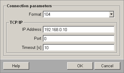
Figure 5. For IEC 101: 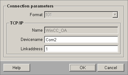
-
Start the driver in the console for driver number 1 - the WCCILsim simulator must not be running:
WCCOAiec - num 1 -
Once a connection has been established to the server the log viewer (e.g. on the client system) displays a message:
WCCOAiec (1), 2002.06.25 11:53:31.007,SYS ,INFO , 0, "", Got connection to WinCC_OAWCCOAiec (1), 2002.06.25 11:53:31.016,IMPL ,INFO , 0, "", Connection to WinCC_OA initialized -
Enter the addresses to your IEC for IEC_TARGET (see Parameters panel). In this example, two data point elements were used as addresses, one to send bit values and one for analog values: ExampleDP_AlertHdl1 for bit values, ExampleDP_Arg1 for analog values. These elements must be created on the two systems and contain the config _address containing the peripheral address and config _original used to send the values.
Define transfer direction here. The master is set to output direction, the slave to input:
Figure 6. IEC driver address configuration panel for bit values (master) 
Figure 7. IEC driver address configuration panel for bit values (slave) 
Figure 8. IEC driver address configuration panel for analog transfer (master) 
Figure 9. IEC driver address configuration panel for analog value transfer (slave) 
-
Open the server online value configuration panel, e.g. for the analog value, and send some values.
The values are set on the client. Open the associated panel on the client and observe the online values. If you enter a new value on the server panel, it is applied to the client panel.


