IEC driver details
This chapter is intended for advanced WinCC OA users who want details on frame transmission modes and their mapping on WinCC OA.
The following diagram illustrates how an ASDU (application service data unit = data package) is structured according to the standard. The individual octets of the addresses and identifiers are shown as rectangles.
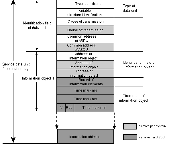
According to the standards, the application service data unit ( ASDU) consists of the data unit identification field with:
-
Variable structure qualifier set by driver
-
Common address of ASDU corresponds to Common Address
-
Information objects: The octets of the information object address correspond to HB, MB and LB of the Information Object Address. The information elements are the actual readings.
The individual octets of the frames are made up as shown in the diagram (one octet corresponds to one rectangle). Please see the standards for a detailed description of the octets.
Below, UI [1..8] always means one byte with a range 0 - 255 bits, UI[1] is 2^0, UI[8] is 2^7. BS[1] means that exactly one bit can be set at the first position of the octet.
Type identification
The type identification octet specifies the structure, type and format of the information object.
Type identification UI [1...8]<1..255>
| 2^7 | 2^0 |
<1..127>: compatible range for standard specifications
<128..135>: reserved for message routing ("private" range)
<136..255>: for special applications ("private" range)
Please see the section on Compatibility for details on the type identifications used in WinCC OA.
Variable structure qualifier
The variable structure qualifier contains the number of information objects or elements and the SQ bit ("Single"/"Sequence") that specifies the address type of the following information objects or elements.
Structure qualifier octet:
| SQ | 2^0 |
-
Number: UI7[1..7]<0..127>: 0 means no information object contained, <1..127> the number of information objects.
-
SQ: BS1[8]<0..1> Single/Sequence
<0>: Address of a single element or combination of elements from a number of information objects of the same type.
<1>: Address of a sequence of information elements in a single object of an ASDU.
SQ<0> and N<0..127>: Number of information objects
SQ<1> and N<0..127>: Number of information elements in a single object of an ASDU.
The variable structure qualifier is set/interpreted by the driver. That means that there is no need to configure it and so it is irrelevant for the user.
Cause of transmission
The ASDU forwards the cause of transmission (spontaneous, periodical, etc.) to a specific application task (program) for further processing. The octet contains the cause, job confirmation (positive, negative), a test bit (to check transfer without influencing the process) and the originator address:
| T | P/N | 2^5 | 2^0 | ||||
| Originator address | |||||||
-
Cause: UI6 [1..6]<0..63>; 0 undefined, <1..63> cause identification, <1..47> for the compatible range (as per standard), <48..63> private range for special use
-
P/N: BS[7]<0..1>; 0 positive confirmation, 1 negative confirmation
-
T: BS[8]<0..1>; 0 no test, 1 test
-
Originator address: UI8[9..16]><0..255>; <0> not specified, <1..255> number of originator address
Please refer to the Compatibility section for details on the compatible range. Please see the standard for a detailed description of causes of transmission.
The cause of transmission is either defined by the driver automatically or set by the user. The standard behavior is implemented as follows:
A cause of transmission 6 (activation) is used when the driver sends commands (C_* messages). When the driver sends messages (M_* messages) the cause of transmission is 3 (spontaneous).
The input-sided cause of transmission is implemented as follows:
20 <= COT <= 36 ... Message because of GA (the GA bit in PARA panel is set)
COT == 5 ... Message because of a single query (EA bit in PARA panel is set)
other COT ... spontaneous Message or another reason (no bit is set).
In order to distinguish between the messages (M_* messages) that are normally sent by WinCC OA (this means cause of transmission spontaneous = 3) and messages that are sent as a result of a IGQ (Inverse General Query)there is the config entry useCOTGQ (see also possible config entries of the IEC driver). When the value of the config entry is "Yes" (default is "No") the COT (= Cause of Transmission) 20 (queried cia GA) is used for all messages that are sent because of an IGQ, the COT 37 (queried via general counter query) is used for counter messages. Normally the Cause of transmission is 3.
There exist two possibilities fore mapping the COT manually:
The usage of user bytes
The usage of a COT address has the drawback that a additional data point element incl. a special COT peripheral address is required (see address type in Panel for defining the peripheral addresses of the IEC driver).
The COT address
Since the WinCC OA release 3.8 it is possible to map the "Cause Of Transmission" (COT) on user bytes. This new method should be preferred to the COT address in the future.
In order to map input-sided the COT and the origin address on WinCC OA, the config entries UserByteCOT and UserByteOrigin have to be set on the number of the used user byte. By default the value is "0" and no mapping occurs. With the following config entries the COT is mapped on the user byte 3 and the origin address on the user byte 4.
UserByteCOT = 3
UserByteOrigin = 4
In order that the user byte values will be integrated in the telegram out-sided, the config entries ConnUserByteCOT and ConnUserByteOrigin have to be set on the number of the used user byte. Like mapping via ConnUserByteQ it applies also here that every change of the corresponding user byte (or of the contained user bit) triggers a hotlink and sends the value to the peripheral address. In order to avoid multiple telegrams the _original.._value and the corresponding _original.._userbyte<x> have to be set in a dpSet() for every application. That means that if the value, COT and the origin address shall be changed at the same time, this must be done using dpSet() in order to avoid telegrams with intermediate states.
Compatibility of COT addresses in the user byte variant
Input-sided:
Up to now it was possible to configure for each COT and each origin address a "COT peripheral address". This have the continuing ability, even if UserByteCOT or UserByteOrigin are unequally 0, however, it makes no sense to combine these to variations in a new project.
Output-sided:
Up to now there were also "COT peripheral addresses" on the output side. They continue working, when ConnUserByteCOT and ConnUserByteOrigin are set to 0. If an entry is unequally 0, so only the information from the user byte will be integrated in a telegram.
If the user byte for the COT set to 0, so the default COT from the driver will be used.
Common address of ASDU = region, component
The common address is common to all objects in an ASDU. The global address is an address sent to all stations of a particular system.
Common address: UI8[1..16]<0...65535>
| 2^7 | 2^0 | ||||||
| 2^15 | 2^8 |
<0>: not used
<1...65534>: station address
<65535>: global address
ASDU with an "address to all" in control direction must be answered in monitor direction with ASDU that contain the specified common address (station address).
Information objects = Information Object Address
The address of the information object (1, 2 or 3 octets) is used as the destination address in control direction and as source address in monitor direction. Depending on the number of octets the address of the information objects is:
| 2^7 | 2^0 | ||||||
| 2^15 | 2^8 | ||||||
| 2^23 | 2^16 |
UI [1...8]<1...255>: HB
UI [1-16]<1...65535>: MB
UI [1-24]<1...16777215>: LB
Please refer to the IEC 60870-5-104 standard for a detailed description.
Number of ports and re-establishing the connection
In theory the number of ports (serial interfaces), which can be handle by the IEC 101 driver, is depending on the possible serial interfaces of the corresponding operating system. For Windows the number of ports (serial interfaces) is limited to 255.
The theoretical number of slaved in a unbalanced mode is defined by the maximum value of the link address.
The specification is "theoretical", because in most cases a maximum number has a bad influence on the performance.
In case of disconnection to the peripheral address, the driver tries periodically to re-establish the connection.
General query
Automatic general query at driver start or redundancy switch IEC
The properties of the general query can be specified with the config autoGQ entry (for details see chapter Possible IEC driver config entries). The behaviors of the IEC driver 104 and 101 are identically. An execution of a general query requires that the common object addresses in the local/global list are explicitly defined, i.e. there a no wildcards present.
Access to different frame types via subindex
The table shown below contains the information of the existing frame types and frame fields that you can access via subindex. In this context note the following points:
Quality Information
The quality information in the command direction (C_* as well as M_* frame types can be sent to the command direction) is built for some frames as OR relation of the value that is specified via the subindex. The value is built with the value from the address (e.g. M_SP_NA_1 or C_SC_NA_1). This is the case if the data or a part of the data and the quality information are included in the same byte. In case of other diagrams the value can only be built from the address via the Quality Information (e.g. M_BO_NA_1 or C_SE_NA_1).
When the quality information is input-sided mapped on user bits, then the user bits will be set on all relevant subindices.
DPE type
The DPE type does not have to be set like shown in the table because a type conversion is also made. This way you can use e.g. the type int instead of bool. The int can get the values 0 or 1. In case of incompatible types an error message is shown during the transformation. You should of course use the types of the table unless there are some other reasons against the use.
Special subindices
For some frame types there are special subindices that facilitate the access to data. This way it is e.g. possible to access the DPI field as "unsigned int" via the subindex 8 in case of the M_DP_NA_1 telegram. This means that you do not have to define two DPEs for DPI bit 0 and DPI bit 1.
The user byte value from a data point element with lowest subindex is written output-sided on the data point elements with higher subindices.
When defining the peripheral address you have to configure the direction "Output (group)" for the following frame types (listed in the table)!
| Telegram | Transf. | Item | SI | DPE Type | Note |
|---|---|---|---|---|---|
|
M_SB_NA_1 (1) M_SB_TA_1 (2) M_SB_TB_1 (30) |
SIQ | SPI | 0 | bool |
Input-sided BL, SB, NT and IV can be also mapped on the corresponding user bits. Output-sided the quality bits can be set in the user byte ConnUserByteQ . |
| BL | 4 | bool | |||
| SB | 5 | bool | |||
| NT | 6 | bool | |||
| IV | 7 | bool | |||
|
M_DP_NA_1 (3) M_DP_TA_1 (4) M_DP_TB_1 (31) |
DIQ | DPI bit 0 | 0 | bool | |
| DPI bit 1 | 1 | bool | |||
| BL | 4 | bool |
Input-sided BL, SB, NT and IV can be also mapped on the corresponding user bits. Output-sided the quality bits can be set in the user byte ConnUserByteQ . |
||
| SB | 5 | bool | |||
| NT | 6 | bool | |||
| IV | 7 | bool | |||
| DPI as uint | 8 | uint | DPI as unsigned integer, values from 0-3 | ||
|
M_ST_NA_1 (5) M_ST_TA_1 (6) M_ST_TB_1 (32) |
VTI | value | 0 | int |
Value Input-sided BL, SB, NT and IV can be also mapped on the corresponding user bits. Output-sided the quality bits can be set in the user byte ConnUserByteQ . |
| T | 1 | bool | Display of Intermediate position | ||
|
M_BO_NA_1 (7) M_BO_TA_1 (8) M_BO_TB_1 (33) |
BSI | bit[i] | 0-31 | bool |
Input-sided BL, SB, NT and IV can be also mapped on the corresponding user bits. Output-sided the quality bits can be set in the user byte ConnUserByteQ . |
| OV | 32 | bool | |||
| BL | 36 | bool | |||
| SB | 37 | bool | |||
| NT | 38 | bool | |||
| IV | 39 | bool | |||
| bit pattern | 40 | bit32 | complete bit pattern | ||
|
M_ME_NA_1 (9) M_ME_TA_1 (10) M_ME_ND_1 (21) M_ME_TD_1 (34) |
NVA | value | 0 | float |
Input-sided BL, SB, NT and IV can be also mapped on the corresponding user bits. Output-sided the quality bits can be set in the user byte ConnUserByteQ . |
| OV | 1 | bool | |||
| BL | 5 | bool | |||
| SB | 6 | bool | |||
| NT | 7 | bool | |||
| IV | 8 | bool | |||
| M_ME_ND_1 (21) | NVA | value | 0 | float | Type 21 has no quality information. |
|
M_ME_NB_1 (11) M_ME_TB_1 (12) M_ME_TE_1 (35) |
SVA | value | 0 | int |
Input-sided BL, SB, NT and IV can be also mapped on the corresponding user bits. Output-sided the quality bits can be set in the user byte ConnUserByteQ . |
| OV | 1 | bool | |||
| BL | 5 | bool | |||
| SB | 6 | bool | |||
| NT | 7 | bool | |||
| IV | 8 | bool | |||
|
M_ME_NC_1 (13) M_ME_TC_1 (14) M_ME_TF_1 (36) |
R32 | value | 0 | float |
Input-sided BL, SB, NT and IV can be also mapped on the corresponding user bits. Output-sided the quality bits can be set in the user byte ConnUserByteQ . |
| OV | 1 | bool | |||
| BL | 5 | bool | |||
| SB | 6 | bool | |||
| NT | 7 | bool | |||
| IV | 8 | bool | |||
|
M_IT_NA_1 (15) M_IT_TA_1 (16) M_IT_TB_1 (37) |
BCR | counter value | 0 | int |
Input-sided CY, CA and IV can be also mapped on the corresponding user bits. Output-sided the quality bits incl. SQ can be set in the user byte ConnUserByteQ. SQ cannot be mapped input-sided, because it is an integer value. |
| SQ | 1 | uint | |||
| CY | 2 | bool | |||
| CA | 3 | bool | |||
| IV | 4 | bool | |||
|
M_EP_TA_1 (17) M_EP_TD_1 (38) |
SEP | ES bit 0 | 0 | bool | You cannot access ES as int at the moment. There is no implementation. |
| ES bit 1 | 1 | bool | |||
| EI | 3 | bool |
Input-sided BL, SB, NT and IV can be also mapped on the corresponding user bits. Output-sided the quality bits can be set in the user byte ConnUserByteQ . |
||
| BL | 4 | bool | |||
| SB | 5 | bool | |||
| NT | 6 | bool | |||
| IV | 7 | bool | |||
| elapsed time | 8 | time | |||
| - | 9 | unint (bit32) | Allows to map reference data from the telegrams on a data point element of the uint (bit32) type. Thereby the bits ES, EI, BL, SB, NT und IV can be mapped on a data point element of the type bit32. | ||
|
M_EP_TB_1 (18) M_EP_TE_1 (39) |
SPE | GS | 0 | bool | |
| SL1 | 1 | bool |
Input-sided SL1, SL2, SL3, SIE and SRD can be also mapped on the corresponding user bits. Output-sided the quality bits can be set in the user byte ConnUserByteQ . |
||
| SL2 | 2 | bool | |||
| SL3 | 3 | bool | |||
| SIE | 4 | bool | |||
| SRD | 5 | bool | |||
| relay time | 8 | time | |||
| - | 9 | unint (bit32) | Allows to map reference data from the telegrams on a data point element of the uint (bit32) type. Thereby the bits GS, SL1, SL2, SL3, SIE and SRD can be mapped on a data point element of the type bit32. | ||
|
M_EP_TC_1 (19) M_EP_TF_1 (40) |
OCI | GC | 0 | bool | |
| CL1 | 1 | bool |
Input-sided CL1, CL2 and CL3 can be also mapped on the corresponding user bits. Output-sided the quality bits can be set in the user byte ConnUserByteQ . |
||
| CL2 | 2 | bool | |||
| CL3 | 3 | bool | |||
| relay opening time | 8 | time | |||
| - | 9 | unint (bit32) | Allows to map reference data from the telegrams on a data point element of the uint (bit32) type. Thereby the bits GC, CL1, CL2 and CL3 can be mapped on a data point element of the type bit32. | ||
| M_PS_NA_1 (20) | BSI | bit[i] | 0-31 | bool | single bits |
| bit pattern | 40 | bit32 | complete bit pattern | ||
|
C_SC_NA_1 (45) C_SC_TA_1 (58) |
SCO | SCS | 0 | bool | |
| QU bit 0 | 2 | bool |
Output-sided QU and S/E can be set in the user byte ConnUserByteQ. Input-sided the subindices must be used. |
||
| QU bit 1 | 3 | bool | |||
| QU bit 2 | 4 | bool | |||
| QU bit 3 | 5 | bool | |||
| QU bit 4 | 6 | bool | |||
| S/E | 7 | bool | |||
|
C_DC_NA_1 (46) C_DC_TA_1 (59) |
DCO | DCS bit 0 | 0 | bool | |
| DCS bit 1 | 1 | bool | |||
| QU bit 0 | 2 | bool |
Output-sided QU and S/E can be set in the user byte ConnUserByteQ. Input-sided the subindices must be used. |
||
| QU bit 1 | 3 | bool | |||
| QU bit 2 | 4 | bool | |||
| QU bit 3 | 5 | bool | |||
| QU bit 4 | 6 | bool | |||
| S/E | 7 | bool | |||
| DCS | 8 | uint | DCS as unsigned integer, values from 0-3 | ||
|
C_RC_NA_1 (47) C_RC_TA_1 (60) |
RCO | RCS bit 0 | 0 | bool | |
| RCS bit 1 | 1 | bool | |||
| QU bit 0 | 2 | bool |
Output-sided QU and S/E can be set in the user byte ConnUserByteQ. Input-sided the subindices must be used. |
||
| QU bit 1 | 3 | bool | |||
| QU bit 2 | 4 | bool | |||
| QU bit 3 | 5 | bool | |||
| QU bit 4 | 6 | bool | |||
| S/E | 7 | bool | |||
| RCS | 8 | uint | RCS as unsigned integer, values from 0-3 | ||
|
C_SE_NA_1 (48) C_SE_TA_1 (61) |
NVA | value | 0 | float |
QL1-7 -> Subindex 1-7 S/E -> Subindex 8 |
|
C_SE_NB_1 (49) C_SE_TB_1 (62) |
SVA | value | 0 | int |
QL1-7 -> Subindex 1-7 S/E -> Subindex 8 Output-sided QU and S/E can be set in the user byte ConnUserByteQ. Input-sided the subindices must be used. |
|
C_SE_NC_1 (50) C_SE_TC_1 (63) |
R32 | value | 0 | float |
QL1-7 -> Subindex 1-7 S/E -> Subindex 8 Output-sided QU and S/E can be set in the user byte ConnUserByteQ. Input-sided the subindices must be used. |
|
C_BO_NA_1 (51) C_BO_TA_1 (64) |
BSI | bit[i] | 0-31 | bool |
single bits This type does not have a quality information. |
| bit pattern | 40 | bit32 | complete bit pattern | ||
| C_IC_NA_1 (100) | Interrogation | QOI | 0 | uint | |
| C_CI_NA_1 (101) | Interrogation | QCC | 0 | uint | |
| C_RD_NA_1 (102) | Empty | - | - | bool | The data in the frame are fix coded. If you receive that kind of frame the value 1 is set on the data point. |
| C_CS_NA_1 (103) | CP56 | CP56 time | 0 | time | |
|
C_TS_NA_1 (104) C_TS_TA_1 (107) |
FBP | - | - | bool | The data in the frame are fix coded. If you receive that kind of frame the received value is set on the data point. |
| C_RP_NA_1 (105) | Interrogation | QRP | 0 | uint | |
| P_ME_NA_1 (110) | NVA | value | 0 | float | Output-sided the parameter qualifier KPA, LPC and POP can be set in the user byte ConnUserByteQ. |
| P_ME_NB_1 (111) | SVA | value | 0 | int | Output-sided the parameter qualifier KPA, LPC and POP can be set in the user byte ConnUserByteQ. |
| P_ME_NC_1 (112) | R32 | value | 0 | float | Output-sided the parameter qualifier KPA, LPC and POP can be set in the user byte ConnUserByteQ. |
| P_AC_NA_1 (113) | Empty | - | - | bool | The data in the frame are fix coded. If you receive that kind of frame the value 1 is set on the data point. |
|
M_IT_ND_1 (230) M_IT_TD_1 (231) |
eight byte floating point counter value | counter value | 0 | float | |
| SQ | 1 | uint |
Sequence number Input-sided SQ cannot be mapped onuser bits, because it is an integer value. |
||
| CY | 2 | bool |
Input-sided CY, CA and IV can be also mapped on the corresponding user bits. Output-sided the quality bits incl. SQ can be set in the user byte ConnUserByteQ. |
||
| CA | 3 | bool | |||
| IV | 4 | bool | |||
|
M_IT_NC_1 (240) M_IT_TC_1 (241) |
6 octet BCD | 0 | double | 6 octet counter value | |
| 6 octet BCD | 1 | uint |
Sequence number Input-sided SQ cannot be mapped onuser bits, because it is an integer value. |
||
| 6 octet BCD | CY | 2 | bool |
Input-sided CY, CA and IV can be also mapped on the corresponding user bits. Output-sided the quality bits incl. SQ can be set in the user byte ConnUserByteQ. |
|
| 6 octet BCD | CA | 3 | bool | ||
| 6 octet BCD | IV | 4 | bool | ||
| C_SE_NZ_1 (242) | 6 octet BCD | 0 | double | 6 octet counter value | |
| 6 octet BCD | 1 | uint | not used | ||
| 6 octet BCD | 2 | bool | not used | ||
| 6 octet BCD | 3 | bool | not used | ||
| 6 octet BCD | 4 | bool | S/E |
Private frame types
The frame type 135 belongs to the private types. I.e. the content of a BLOB DPE is transmitted and no interpretation of the data takes place. This is valid for the IEC 101 and 104 driver.
This frame type functions only with DPEs from type blob. Additionally you have to set the Information Object Address to 0.0.135.
Consistency check of frames
IEC 101
The following is being checked:
-
Consistent frame header
-
Checksum
In the event of an error the connection is reinitialized as a consequence.
IEC 104
The following is being checked:
-
Consistent frame header
In the event of an error the connection is reinitialized as a consequence.
If the calculation of the checksum fails, the connection will be initialized newly. In this case an normal error message is shown, that the connection is lost. With the debug level "-dbg 27" you can have a closer look whether the checksum causes the error.
Optimization of the data throughput
Telegrams are packed into one telegram when they are sent. The system checks whether TYP, COT (= Cause of Transmission) and COA (Common Object Address) of the last telegram match these of the current telegram. If they match, the information object is added to the last telegram in the queue, if this is possible when the length is considered. It will be tried to add the IOA on the last telegram in the queue, in order to secure that one telegram does not pass another.
Possible error messages when using the IEC driver
WCCOAiec (1), 2005.02.26 17:27:25.622, PARAM,SEVERE, 54, Unexpected
state, IecResources, DP-Element does not exist , _Iec_1.FileTransfer.Command:_original.._value
WCCOAiec (1), 2005.02.26 17:27:25.623, PARAM,SEVERE, 54, Unexpected state, IecResources, DP-Element does not exist , _Iec_1.FileTransfer.Status:_original.._value
These messages indicate that there is an inconsistency between the driver version and the internal data points or data point types.
WCCOAiec (1), 2005.02.27 16:27:19.990, PARAM,WARNING, 54, Unexpected state, IecTgLayer, generalQuery, Check format of local/global list entry, COA not correctly specified *.*.*.*.*
*.*.*.*.* is specified in the gloabal/local IEC list. The log message is a warning. A GQ via the internal data point or via the config entry autoGQ > 0 is not possible. To execute a GQ, both entries (Region + Component) have to be unequal to "*".


