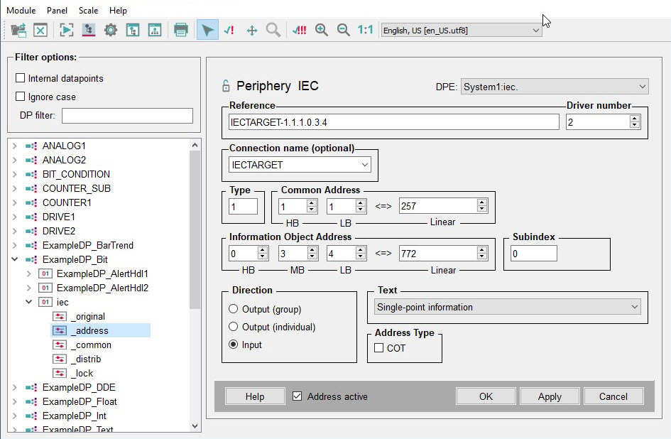
Panel for defining the Peripheral Addresses of the IEC Driver
The panel described below allows you to configure a peripheral address for the IEC driver.
The address ("reference string") can be entered directly in the "Reference" field or by using the spin buttons for the various components. You can create the following types of addresses:
-
Type. Common Address. Information Object Address
-
Type: Quality. Common Address. Information Object Address
-
Connection_name-Type.Common Address.Information Object Address
-
Connection_name-Type.:Quality.Common Address.Information Object Address
I.e., Quality is only specified if the string contains a colon ":", otherwise it is 0.
-
Driver number: Number of the associated manager that starts the IEC (e.g. - num 4).
-
Connection name (optional)
All connection names, which have a data point of the type _IecConnection, are available in the combo box.
The behavior is specified by the direction the values of the data point elements are sent: Output - data is transferred only over this connection whose name was specified. Input - data is written to data point elements only if a telegram is received over the connection specified in the address.
-
Type (frame type)
The type is automatically set in the "Text" combo box when you select the type of a frame. It is the number of the frame as described in the IEC standard, e.g. 1 for single-point information without a time tag or 137 for 16 single-point informations (see Compatibility).
-
Create an appropriate peripheral address and set the associated data point.
-
By using the _Iec data point (see chapter Internal data points of the IEC driver)
-
By using the _IecConnection data point (see chapter Internal data points of the IEC driver)
There are 3 different possibilities to send system telegrams:
Low-level (old/new comparison) cannot be configured for the IEC driver. It is not necessary since for IEC generally only changes are transmitted.
You cannot define two peripheral addresses that only differ in terms of the type of frame for the control direction. Although the peripheral address contains the type, peripheral addresses that only differ in terms of the type of frame are regarded as "identical" addresses. System telegrams (100 - 107) where the telegram type is also taken into account, are an exception.
-
Text (frame type): select the type (frame type) here.
-
Quality Information
This entry is optional and quality 0 is sent by default. The entry is a number between 0 and 255. Which values are meaningful depends on the format of the frame (see IEC driver details). The entry can only be set for the output (command direction). For the input direction you can map the quality information to WinCC OA user bits via config entries or to the data point elements via the subindex. See chapter Quality identification for details on how to use the quality information and how to map these bits to WinCC OA user bits.
You can only configure the quality for a DPE with subindex 0 in the peripheral address! Qualities set for higher subindices are ignored.
-
Address Type
With this check box you can map the value of the cause of transmission (=COT) to a DPE. To do so: Configure an IEC peripheral address for a DPE (on this DPE do not activate the check box). For a second DPE configure the same address and additionally activate the check box for transmitting the COT. This configuration for "mapping the cause of transmission" is valid for both an input and an output address. If a value is sent in message direction to the control system, you can see the specific value for this address on the first DPE and the value for the COT on the second DPE.
Note that if you configure an output address with COT, save the value of the COT by clicking "Apply" in the configuration panel first (the value is saved in the driver). Afterwards you can send the command, spcified on the second DPE, to the periphery with the specific COT. After a restart of the driver you must set the value of the COT again. Otherwise the default value of the COT is used! the best way to set the COT DPE and the value DPE in one dpSet() is by using a script. Se the COT DPE first. This means that only one message is sent from the Event Manager to the driver.
-
Common Address, Information Object Address
System address notation (HB = High Byte, LB = Low Byte, MB = Medium Byte). Common Address sets the parameters for the common address of the ASDU (application service data unit = data package). The Information Object Address parameters define the address of the information object (see IEC driver details).
To find out the region and component for the WinCC OA IEC address, proceed as follows:
The IEC address in WinCC OA has the following format: "Type. Common Address. Information Object Address"
- Type is the IEC telegram type
- Common Address (HB.LB (HB = High Byte, LB = Low Byte): these are the parameters for "common address of the ASDU" (application service data unit = data package) .
- Information Object Address (=IOA) (HB = High Byte, LB = Low Byte, MB = Medium Byte))
The size of the common address of the ASDU is 2 bytes
In order to get the (Region = High byte, component = low byte) of the ASDU proceed as follows:
1- The common address of the ASDU must be converted into a hex number.
2- The component is the lowest byte (low byte) in this hex number.
3- The region is the highest byte (high byte) in this hex number.
4- The component and region must be converted into a decimal number.
For example: The common address of the ASDU 270 -> as hex number: 10E -> HB = 1 and LB = OE -> HB (Region) = 1 and LB (component) = 14.
The Common Address and Information Object Address can be input also linearly.
-
Subindex
Subindex is widely used in the IEC driver to access the data in a telegram. See the details for each telegram on the page IEC driver details. For the private SSI telegram types the same mapping applies to frames (type 135-141, 160) as to the SSI driver, i.e. the same use of the subindex and the same DP types. The floating time for command 160 (= Single command with output time) is specified in the quality identification. Unlike the SSI driver, this is not an index in a table, but must be specified the way it is supposed to be appear in the frame.
-
Bits
The length of the bitstring. This entry is only required for frames of the type "Bitstring of 32 bit" and Bitstring of 32 bit with time tag". When a bitstring transformation is selected and the subindex has the value 40, the value in the field "Bits" will be ignored and all 32 bits will be mapped.
-
Direction
The Transfer Direction radio box specifies whether data point element values are sent in the control direction (output) or in the message direction (input). For the control direction there is a further choice between group and single registration. Group registration always sends the values of all elements (subindices) of a peripheral address (i.e. Common Address and same Information Object Address.); for single-point information only for the respective data point element (subindex). Apart from some special cases for private types group registration must be selected to send correct telegrams.
-
Address active
The Address active option is checked. The driver uses the address (seeReference tables). Although a disabled address exists, and although the attributes can be set and queried, the driver does not use them. I.e., you cannot send or receive any values of this DP to/from the remote control system.
Special features
The system telegram types 100-107 can also be mapped to normal data point elements with a peripheral address. In this case the Information Object Address (HB and MB) are set to 0 and the Information Object Address (LB) is set to the type number (100-107). Although the LB of the information object address is also 0 in the frame, in order to distinguish between different system frames with the same common address, the LB is "faked" internally in the driver and set to the telegram type. So for the input the LB of the IOA must be set to the type number in the peripheral address. For the output either 0 or the type number can be specified.
Example
100.Common Address.0.0.100
As usual, Common Address is from 0-255.
For the following telegram types, the assignment of input addresses only works if the information object address is set to 0.0.<telegram type>:
C_IC_NA_1, C_CI_NA_1, C_CS_NA_1, C_TS_NA_1, C_RP_NA_1, C_CD_NA_1, C_TS_TA_1


