Defining a Native EIP PLC peripheral address
This chapter describes the configuration of a peripheral address for a native EIP PLC.
Reference
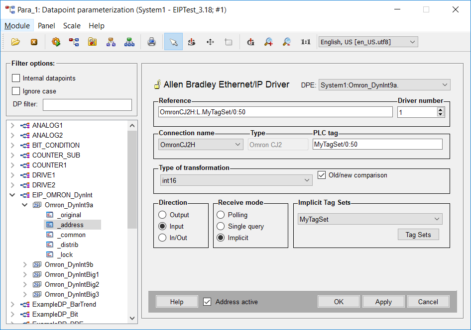
The completely formatted address string. You can enter the address directly in the Reference text field, or create it via the separate fields.
Reference Syntax
<device>:L.<logix tag><device>.<logix or pccc tag> is still valid for compatibility reasons, but should not be used
anymore.Driver Number
Must be set to match the corresponding instance of the Ethernet IP driver.
Connection Name
Select the PLC to which this address should be assigned.
Type
The type of the selected PLC (cannot be changed here).
PLC Tag
The exact symbolic tag name used in the PLC. An optional .bit suffix can be added to INT and DINT tags to select a specific bit.
Omitting subscripts from an array tag will access the first element of the array.
When using implicit receive mode the offset and size inside the Tag Set must be defined in the Format <TagSetName>/<offset>[:<size>], e.g.
"MyTagSet/0:50" would mean that it will get its data from the implicit Tag Set called MyTagSet, starting at offset 0 for 50 elements. The offset starts at zero and is mandatory, the
length however is optional and should be used for arrays only.
Type of transformation
Choose the transformation type for this PLC tag from the combo box. You must match the transformation type to the data type of the selected tag in the PLC, or the request will be rejected by the PLC. The possible choices are:
- Int16
- Int32
- Uint16
- Uint32
- Float32
- Char
- String
- Bit
- Bit in word
- Bit in dword
- Blob
- Raw text array
- Bit in Byte
- Float64 (Double)
- Raw Text (16-bit to 2 char string)
Strings are sent with their current text length but are truncated at 82 bytes.
The Raw text array to string transform allows transferring text that is stored in an INT array in the PLC, two characters per element, into a WinCC OA string data point.
It is permitted to read an entire structure into a Blob DPE (up to the configured message size of 512 - 2048 bytes). Logix Blob-reads are not grouped together in polls. Writing Blob DPEs to Logix PLCs is not supported.
"Bit in byte" uses the SINT type within the PLC whereas "Bit in word" uses the type INT.
In case the specific type is not listed above, choose a matching basic type and data length. In WinCC OAthere is no difference between a BCD type, such as UINT_BCD, and its basic type, UINT.
Bit in word and bit in dword allow reading a specific bit of a WORD or DWORD symbol. Therefore, use the optional .bit suffix in the PLC Tag as described above (e.g. MyWord.5 to read bit 5 of MyWord). When using Omron PLCs these transforms do not support writes.
When configuring an address for a dyn datapoint, use the associated basic types. For example, when adding an int16 array the transformation int16 should be used.
The Raw Text transformation can be used to transfer 2-characters of text to or from WinCC OAstring datapoint elements and a 16-bit PLC register. Text defaults to little endian byte order. A swap-bytes checkbox allows reversing alternate bytes.
The "raw text array" transformation is used to transform a PLC array of 2-character text registers to a WinCC OA string datapoint element. When writing a string longer than the PLC’s array, the message will be rejected by the PLC.
Direction
Define if you want to send values of a datapoint element to the PLC (output), or read them from the PLC into the datapoint (input). The In/Out selection allows using both, but should be used with caution.
Receive mode
Choices are:
- Polling - Allows adding this address to a poll group which can then be scheduled.
- Single query – The address is only polled on demand by writing its element name to the _DriverCommon.SQ internal datapoint for the corresponding driver number. These addresses are also polled by the EIP driver during a general query.
- Implicit – Allows high-speed updates of WinCC OA datapoint elements from the PLC without polling. The driver requests a scheduled stream of updates of a specified Tag Set. Once this request is accepted by the PLC it begins sending UDP datagrams containing the data for the entire Tag Set at the specified rate without polling for data.
Poll group
Choose already existing poll groups. If there are no poll groups available you have to create them with the specific polling parameters in a separate panel. The panel is opened by clicking on the Poll groups... button (see Poll groups for more information on poll groups and polling parameters).
Implicit Tag-Sets
Choose an already existing Tag Set for the implicit receive mode. If there are no Tag Sets available, you have to create them with the specific parameters in a separate panel. This panel is opened by clicking on the Tag Sets button (see Ethernet/IP Implicit Messaging for more information on Implicit Messaging).
Address active
The Address active check box is chosen. The address is used by the driver (see Reference tables). An inactive address exists and the attributes can be set and queried but the driver does not use them. This means that no values can be sent to remote system or received from the remote system for this datapoint.
Old/new comparison
You can choose this option only when the transfer direction is set to Input. If the option is chosen the data is only sent in case of changes. The comparison is based on the raw data without conversion.
Data types - additional information
Arrays
By far, the highest transfer rates can be achieved by grouping the data into arrays in the PLC. These arrays can then be read into corresponding dyn data points in WinCC OA, or into separate data points per array element. When using individual array elements, these are automatically grouped into blocks for efficient transfer, up to the MaxGap setting.
- When accessing an array of BOOLs in the PLC, this must be addressed as an array of 32-bit integers. So rather than addressing SomeBits[70] you would instead specify SomeBits[2].6
- It is permitted to read an entire PLC array into a dyn DPE of the corresponding type.
- You can read a range of a PLC array, by using this syntax: ArrayName[starting-index]:range. For example MyIntArray[30]:10 would read elements 30 through 39 of MyIntArray into the configured dynamic data point. If starting at index 0, it is still mandatory to specify MyIntArray[0]:range. MyIntArray:range is not permitted.
- It is permitted to read a multi-dimension PLC array into a WinCC OAdyn data point, although it will be “flattened” into one dimension. If a starting range and index are specified, all dimensions must be specified.
- When reading elements of the same array into separate non-dynamic data points, nearby elements are optimized into blocks for efficient transfer, up to the defined MaxGap number. If reading sparse elements of an array, it may be better to increase MaxGap from its default size of 5.
- If you want to read arrays as a whole without specifying an array length, you have to enable "Read by ID" or trigger the info query manually.
Reading of arrays automatically uses as many transactions as necessary, which allows reading arrays of any size. An array-read is always a separate transaction within the PLC and is not grouped with other tags.
Unlike reads, the whole array needs to fit in one message when writing arrays, which means that the maximum size of the array depends on the element type and on the configured message size.
Using array[index]:length to separate the array into multiple dyn datapoint elements allows you to write bigger arrays.
| DPE type | PLC data type | Transformation | Address example | Notes |
| int | INT | int16 | MyInt | Reads value of MyInt |
| int | INT Array Element | int16 | MyIntArray[5] | Reads value of element 5 of MyIntArray |
| int | DINT | int32 | MyDInt | Reads value of MyDInt |
| int | DINT array element | int32 | MyDIntArray[5] | Reads value of element 5 of MyDIntArray |
| float | REAL | float32 | MyReal | Reads value of MyReal |
| float | REAL array element | float32 | MyRealArray[5] | Reads value of element 5 of MyRealArray |
| bool | BOOL | bit | MyBool | Reads value of MyBool |
| bool | INT | bit in word | MyInt.3 | Reads value of bit 3 MyInt |
| bool | INT array element | bit in word | MyIntArray[5].3 | Reads value of bit 3 of 6th word, i.e. bit 163 |
| dyn int | INT array | int16 | MyIntArray | Reads complete array, requires info query to be performed |
| dyn int | INT array | int16 | MyIntArray[5]:3 | Reads 3 values from MyIntArray starting with element 5 |
| dyn int | DINT array | int32 | MyDIntArray | Reads complete array, requires info query to be performed |
| dyn int | DINT array | int32 | MyDIntArray[5]:3 | Reads 3 values from MyDIntArray starting with element 5 |
| dyn float | REAL array | float32 | MyRealArray | Reads complete array, requires info query to be performed |
| dyn float | REAL array | float32 | MyRealArray[5]:3 | Reads 3 values from MyRealArray starting with element 5 |
| dyn bool | BOOL array | bit | MyBoolArray | Reads a complete array, requires info query to be performed |
| dyn bool | BOOL array | bit | MyBoolArray[5]:3 | Reads 96 bits from MyBoolArray starting at bit 160 |
Program tags
By default, the EIP driver accesses controller-tags in the PLC. You can, however, access program-tags, by using this syntax:
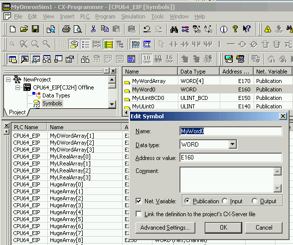
Program:programName.tagNameConfiguration of Omron CJ2 PLCs
An Omron CJ2 series PLC implements Ethernet/IP protocol much like an Allen Bradley Control Logix PLC. All transfers are based on symbolic tag-names. It is not possible to directly specify a low-level block address in the EIP driver. Instead it must be added to the Symbols table in CX-Programmer, and then set as a Net Variable for Publication as shown in the figure below.