Defining a PCCC PLC peripheral address
This chapter describes the configuration of a peripheral address for PCCC-based PLCs such as the PLC5, SLC5, and MicroLogix:
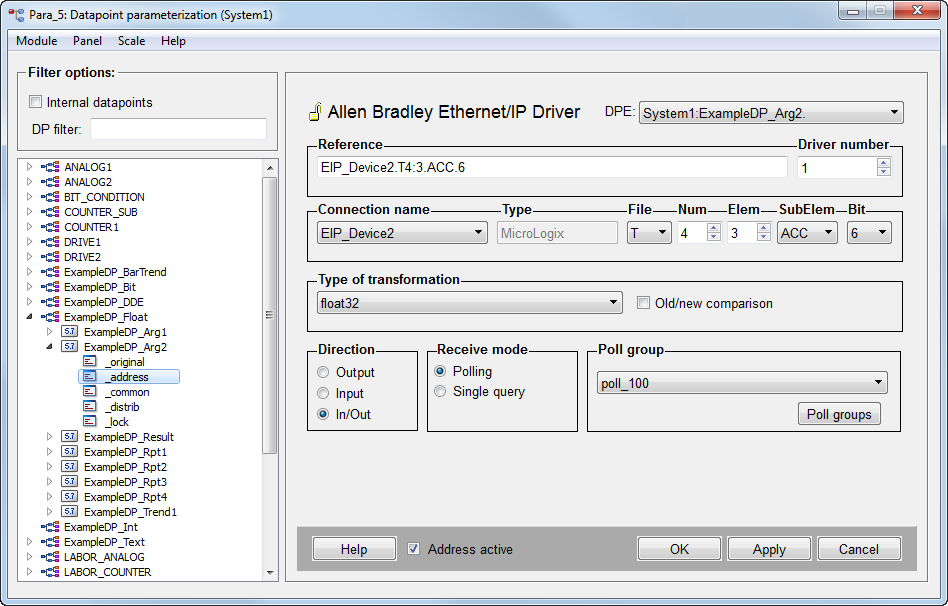
Reference
The completely formatted address string. You can enter the address directly in the Reference text field, or create it via the separate fields. Note that the syntax required by this driver is more standardized than what is allowed by RSLogix. It is therefore advisable to use the separate input fields rather than directly typing in the reference string.
Reference Syntax
<device>:P.<pccc tag>Please note that the previous syntax <device>.<logix or pccc
tag> is still valid for compatibility reasons, but should not be
used anymore.
Driver Number
Must be set to match the corresponding instance of the Ethernet IP driver.
Connection Name
Select the PLC to which this address should be assigned.
Type
The type of the selected PLC (cannot be changed here).
File
In a PCCC-based PLC, the data is grouped by type into one or more instances of each file-type. The file type must always be specified. The possible file types are:
-
N Integers
-
B Bits
-
F Floats
-
S Status bits
-
I Input bits
-
O Output bits
-
A ASCII (2 chars per element) (Not available on MicroLogix)
-
T Timer structure
-
C Counter structure
-
R Control structure
-
ST String (up to 82 bytes)
-
SC Sequential function structure (PLC5 only)
-
PD PID structure (PLC5 only)
Directly writing to Input, Output, or Status bits is not permitted on all PLCs and is never advised.
Num
Instance number for this file-type. An Allen Bradley PLC allows multiple instances of each file-type to be created. The default instance number (if any) for each file-type is shown below. The instance number must always be specified, even if using the PLC’s default value.
-
N 7
-
B 2
-
F 8
-
S 2
-
I 1
-
O 0
-
A no default
-
T 4
-
C 5
-
R 6
-
ST no default
-
SC no default
-
PD no default
Elem
Specifies the element number. This is a zero-based array index. For example if in the PLC you create a file N7 of 100 elements, to access the 3rd element you would set this to 2, resulting in an address string of N7:2. The element number must always be specified.
SubElem
Specifies the sub-element number. This field only appears when a structured file-type is selected, and lists the possible sub-element names for that type. For example, in a timer structure, there are the following sub-elements:
-
EN - Enable-bit
-
TT - Timing-bit
-
DN - Done-bit
-
PRE -Preset value (integer)
-
ACC - Accumulated value (integer)
As you can see, the various sub-elements can be of different data types.
Omitting the sub-element for a structured type would transfer the entire structure, but is only supported when using blob DPEs.
Bit
Specifies the bit number (0-15). This field is optional and only appears when an integer file-type or integer sub-element has been selected. It allows reading or writing a selected bit within a word. Bit numbers above 15 are not supported. For example, rather than trying to read B2:37, you must instead address this as B2:2.5.
Type of transformation
Choose the transformation type for this PLC tag from the combo box. The applicable choices are:
-
Int16
-
Uint16
-
Float32
-
Char
-
String
-
Bit
-
Bit in word
-
Blob
You must match the transformation type to the data type of the selected tag in the PLC, or the request will be rejected by the PLC.
Strings are sent with their current text length but are truncated at 82 bytes.
It is permitted to read or write an entire structure into or out of a Blob DPE.
Writing with the “Bit in word” transformation uses a “masked-write” function, which causes a small read/modify/write cycle within the PLC and should be used with caution.
Direction
Define if you want to send values of a datapoint element to the PLC (output), or read them from the PLC into the datapoint (input). The In/Out selection allows for both to occur, but should be used with caution.
Receive mode
Choices are:
-
Polling - Allows adding this address to a poll group which can then be scheduled.
-
Single query – The address is only polled on demand by writing its element name to the _DriverCommon.SQ internal datapoint for the corresponding driver number. These addresses are also polled by the EIP driver during a general query.
Poll group
Choose already existing poll groups. If there are no poll groups available you have to create them with the specific polling parameters in a separate panel. The panel is opened by clicking on the Poll groups... button (see Poll groups for more information on poll groups and polling parameters).
Address active
The Address active check box is chosen. The address is used by the driver (see Reference tables). An inactive address exists and the attributes can be set and queried but the driver does not use them. This means that no values can be sent to remote system or received from the remote system for this datapoint.
Old/new comparison
You can choose this option only when the transfer direction is set to Input. If the option is chosen the data is only sent in case of changes. The comparison is based on the raw data without conversion.


