How to Create a New Standard Object Library Symbol
The Standard Object Library (Stdlib) provides ready prepared symbol templates, which can be individually adapted and extended according to requirements. For more information on StdLib templates see chapter Symbols.
This chapter describes how a new symbol can be created for a WinCC OA library by using templates. You can create a symbol via the "Standard Object Library Setup" panel or manually. This chapter describes both options: the panel and manual creation.
Create a Symbol
A change state of a symbol is signalled by means of either a change of the background color or the displayed image (images) of a symbol.
Note that the StdLib is only available if you have included the StdLib sub project into your project - see Requirements and installation.
Create a Symbol via the "Standard Object Library Setup" Panel
-
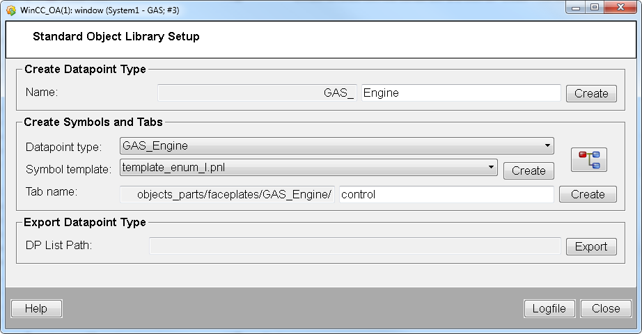
Open the " Standard Object Library Setup Panel" via the System Management panel -> Settings -> Stdlib Development Tool.
-
In order to create a symbol, create a data point type by adding a data point name to the text field "Name" and by clicking "Create" in the Standard Object Library Setup Panel. Then select the data point type and a symbol template from the combo box and click on "Create". The panel allows you to easily create a symbol. The symbol is saved in the project in the /Panels/Objects/[DPName]/ directory. If you select a symbol template via the Standard Object Library Setup Panel, proceed to the step "Symbol Representation".
- After creating the symbol via the panel, proceed to step Symbol representation. The section below describes how to create a symbol manually without the panel.
Create a Symbol Manually
-
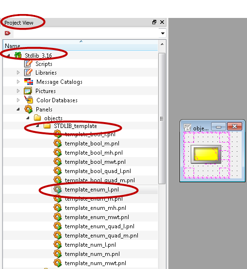
Open the symbol catalog Stdlib (GEDI menu View -> Catalogs -> \Stdlib_<Version>).
The template defines the data type of the symbol. Here (see below) the template template_enum_l was selected. Proceed with the step below.
-
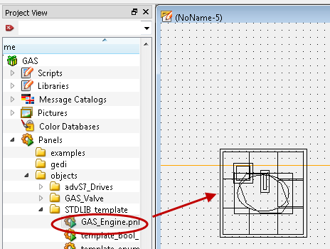
Double-click on the symbol template "template_enum_l.pnl" of the sub directory "STDLIB_template" in order to open the symbol in a new panel.
Figure: Project view and STDLIB_templates
-
Save the symbol as reference "GAS_Engine.pnl" under WinCC_OA_Proj/panels/objects/STDLIB_template via Panel -> Save Panel As..
-
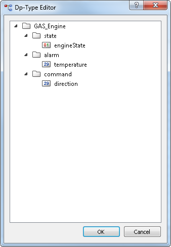
Create a data point type via the PARA module or use an existing data point type. In order to create a Standard Library data point type, read the chapter How to Create Data point Types for the Standard Object Library. Create also data points via the PARA module. For this example, the following data point type was created.
The Stdlib data point type name must contain the prefix „<LIBRARYNAME_IN_CAPITAL_LETTERS>_
e.g. GAS_Engine - see below. When you use the Standard Object Library Setup panel to create a data point type, the prefix and the necessary nodes are automatically added to the data point type. NOTE, however, that you must add the elements (such as "engineState" - see below) to the nodes according to your requirements.
Figure: Data point type "GAS_Engine"
Do not drag the template into the panel via Drag&Drop. Via drag&drop an instance of the symbol (of the reference) is created.
-
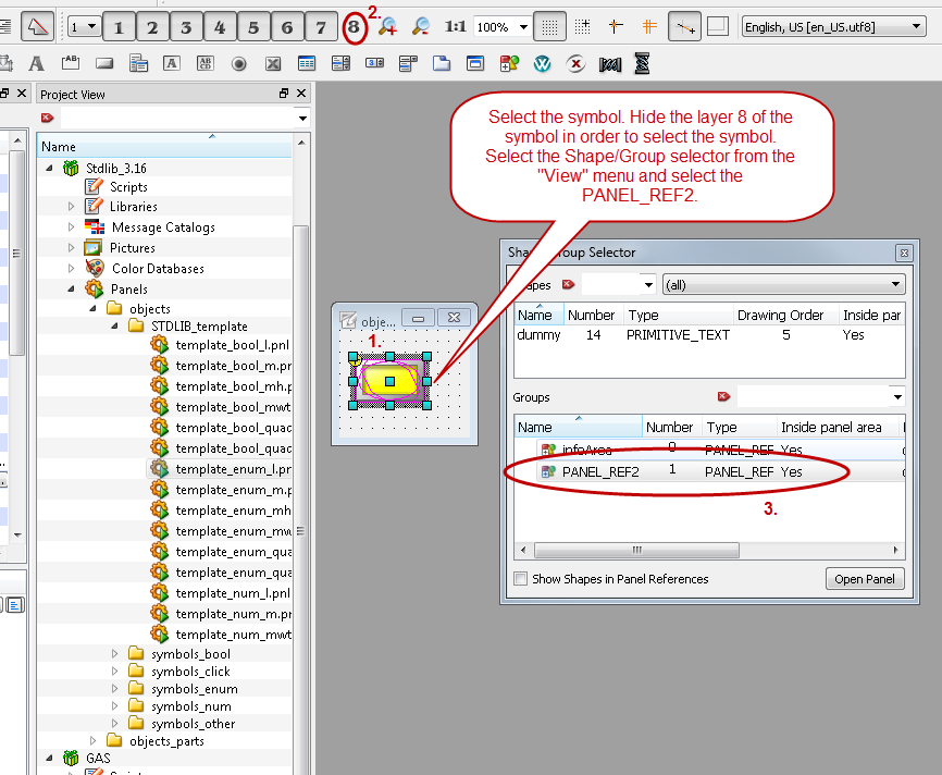
Define the symbol representation. Select the symbol. Then select an object for your symbol via the View menu of GEDI -> Shape/Group Selector. Note that you have to select the symbol and not the frame. In order to select the yellow symbol, hide the layer 8 of the symbol.
Figure: Shape/group selector -> Select panel reference
-
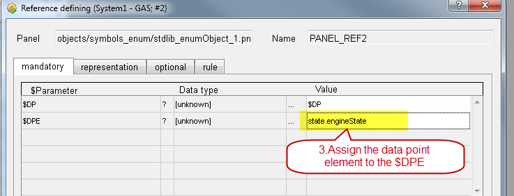
Double-click on the selected symbol. The reference definition window is opened. Assign the data point element state.engineState of the master data point of the before created data point type "GAS_Engine" to the $DPE. Alternatively you can click the "..." button of the attribute "$-Parameter" in the attribute editor in order to open the "Reference definition" panel. The panel contains four tabs, which allow configuring the representation of a symbol. Assign the mandatory value to the $ Parameter $DPE.
Figure: Reference definition - "mandatory tab" - Assign a data point element to the dollar parameter $DPE
-
In the symbol on the tabs of the symbol you can select how a state change should be shown. On the representation tab of the symbol select how a state change should be shown.
-
-
-
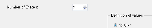
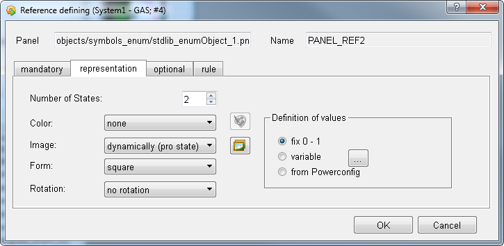
Select for the "Number of States" 2 as well as for the "Definition of values" fix. The Number of States changes the number of values for the "Definition of values".
-
-
Figure: Reference definition - "representation" tab - Number of States/Definition of values
-
-
-
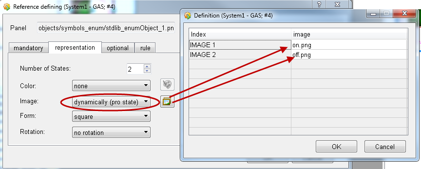
Select for the background color the option "none". Since images are used for this example, no colors are needed.
-
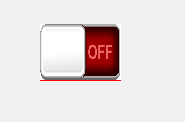
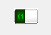
Select for the image the option "dynamically (pro state) and select two different images for the two states. In this example two images "off.png" and "on.png" are used.
-
-
Figure: Reference definition - "representation" tab - Select images


-
-
-
Select the form "square" for the image.
-
In this example the rotation is not used. Therefore, you do not need to change the "Rotation" option.
-
-
Figure: Reference Definition - representation tab
-
In this example no optional dollar parameters or rules are specified since these are not necessary for this symbol.
-
Finish the configuration by clicking the OK button - see figure above.
-
Save the symbol.
-
Add a new panel to graphical editor GEDI and add an instance of the symbol "GAS_Engine.pnl" by drag&drop to the panel:
Figure: Creating a Symbol - Drag&Drop an instance of the GAS_Engine.pnl symbol to a panel
-
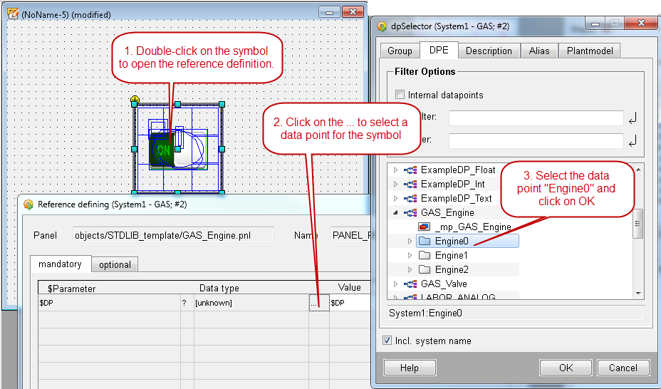
Select a data point for the symbol as shown in the figures below:
Figure: Creating a Symbol - Select a data point
-
Finish the data point selection by clicking OK in the reference definition panel
Figure: Creating a Symbol - Finish the configuration

-
Save the panel with the name "Engine" in the " panels" directory.
-
Open the panel via Quick Test Module of the GEDI:
Figure: Creating a Symbol - Open the panel
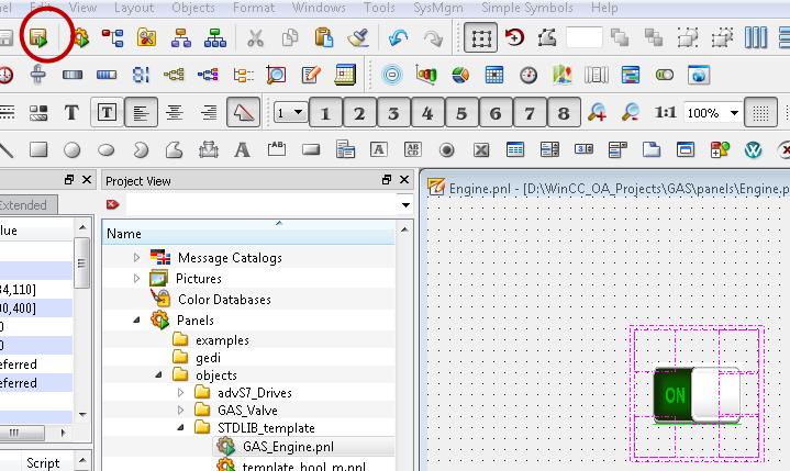
Figure: Open the panel at runtime
-
Set the value of the data point element Engine0.state.engineState to FALSE. The symbol changes the image to the image "off" or in your case to your chosen image.
Figure: Open the panel at runtime