How to create a Standard Object Library
This chapter provides an example for the Standard Object Library. It contains an example for how to build up an object library based on the Standard Library.
This example shows a symbol that displays two states of a boolean data point. You can of course create also symbols for other data point types. For the symbol a Standard Object Library symbol template is used. Depending on what a symbol should display, a symbol template of a boolean, enum or num data type can be used. Also a faceplate that displays the symbol is created in this example. The created library is also exported for reuse. Below you can find the naming conventions of the Standard Object Library and the single steps of this example.
Two Example Options
Note that this example contains two options for creating the standard library data point type as well as for creating a symbol and a faceplate. You can use the "Standard Object Library Setup" Panel and do not need to complete all the steps listed below. If you choose to create the data point type, a symbol and a faceplate manually, complete all the steps below. If you decided to use the "Standard Object Library Setup" Panel, read, however, the steps "Consider the naming conventions of the Standard Object Library" and "Create a Library Project". The step after creating a library project describes the "Standard Object Library Setup" Panel.
Consider the naming conventions of the Standard Object Library:
- The project name is your library name
- The stdlib_hook.ctl is saved under <library name>_hook.ctl. The „hook_std
-
lib_“ in the script is replaced by „hook_<libraryname_in_small_letters>_“ e.g. hook_gas_displayInfoAreaIcon(). If you do not use the Startpanel of the Standard Library, complete this step manually, see the steps Create Library HOOK Functions and
- The Stdlib data point type name must contain the prefix „<LIBRARYNAME_IN_CAPITAL_LETTERS>_“ e.g. GAS_Valve. If you do not use the Startpanel of the Standard Library, complete this step manually, see the steps Create a Data Point Type for the Symbol and Create a Master Data Point.
-
In this documentation the Standard Object Library is often referred to as Stdlib
-
Create a Library Project :
-
-
-
-
-
-
If you use the Startpanel of the Standard Library, proceed to step: Create a Symbol via the "Standard Object Library Setup" Panel, otherwise complete all the steps below.
-
The Startpanel of the Standard Library can be used to complete the following three steps:
-
-
-
-
-
Create a Symbol:
-
-
-
-
-
-
The Startpanel of the Standard Library can be used to complete the following three steps:
Create a Data Point Type for the Symbol,
Select a Symbol Template and Create a Symbol Manually.
To create a symbol, complete also the following steps:
-
-
-
-
-
- Create a Test Panel:
-
Create a Faceplate and Control Panel for
the Faceplate:
- Create a New Faceplate Panel:
-
Authorization Check and Use of the
Created Library:
-
Export Library for Reuse
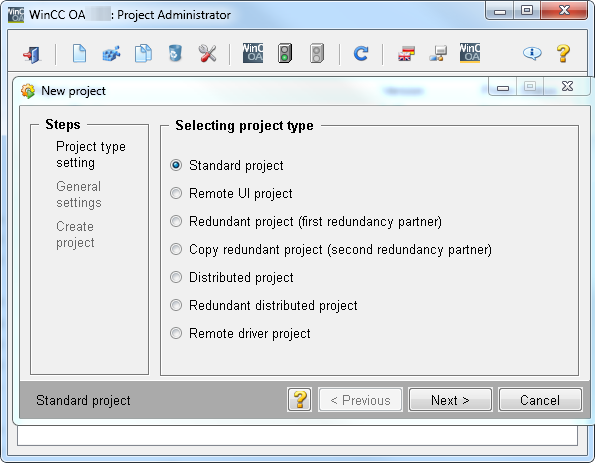
Create a Library Project
-
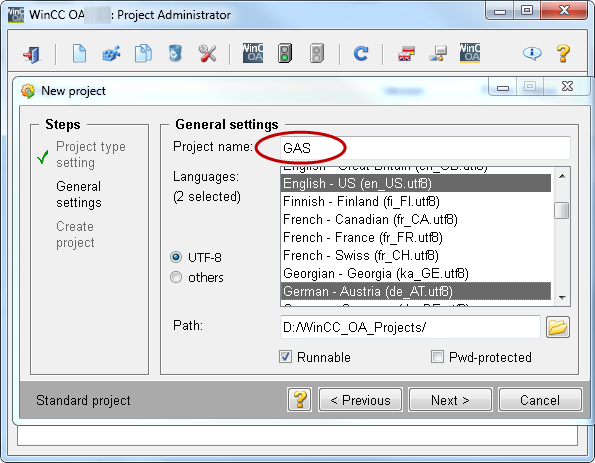
In the WinCC OA project administration, create a new standard WinCC OA project. Specify a name that is later the name of your library. Consider the WinCC OA naming conventions and that _ (underscores) may not be used. All names of the library data point types must use the project name as prefix.
-
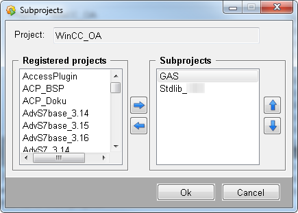
Select the created WinCC OA project and click on the option "Change project settings". In the "Edit project" window, click on the "Integrate subproject" button.
-
Start the project
Create a Symbol via the "Standard Object Library Setup" Panel
This section describes how to use the "Standard Object Library Setup" Panel. If you want to create the data point type and a symbol manually, continue with the step "Import the Stdlib Data Point Types".
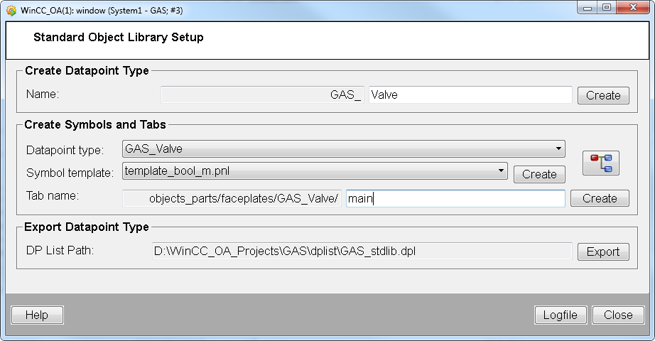
Open the "Standard Object Library Setup" Panel via the System Management panel -> Settings -> Stdlib Development Tool.
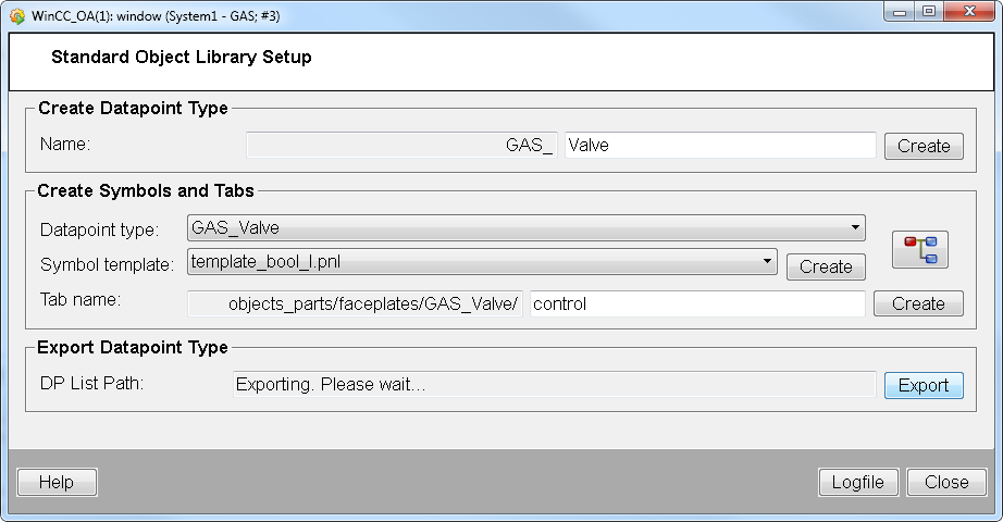
Create a Data Point Type for the Symbol
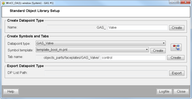
-
Create a data point type for the symbol. The data point type name must contain the prefix <LIBRARY NAME IN CAPITAL LETTERS>. The panel automatically adds the prefix to the data point type (see figure above). Add a data point type name to the text field "Name" and click on "Create".
If you have created several standard library data point types, you can select the data point type from the combo box "Datapoint type". Adjust the data point type according to your requirements. In the following you can see how to adjust the type:
Adjust the Data Point Type for the Symbol
-
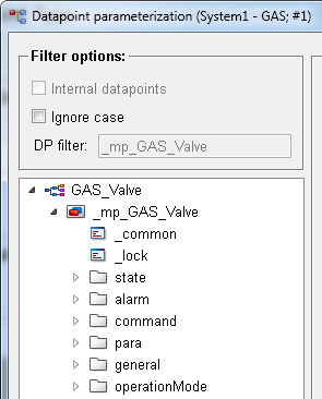
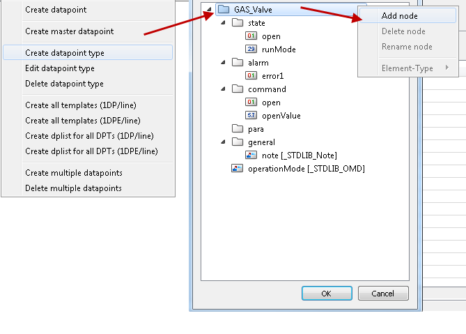
The data point nodes: state, alarm, command, para, general and the notes [_STDLIB_note] and operationMode [_STDLIB_OMD] are automatically added to the data point type.
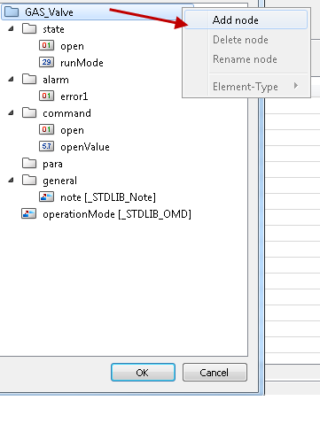
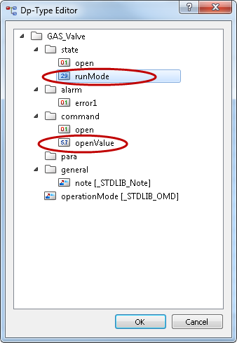
Specific elements must, however, be added to the data point type nodes. In this example elements were added to the state, alarm, command and general nodes. The elements "open" and "runMode", for example, were added to the node "state" . The "alarm" node again contains all numerical alert, warning and/or error alert elements. For the description of the nodes - see chapter How to Create Data point Types for the Standard Object Library.
Select a Symbol Template
This example comprises a symbol that displays the two states of a boolean data point. For the symbol a Standard Object Library symbol template is used. Depending on what a symbol should display, a symbol template of a boolean, enum or num data type can be used.
-
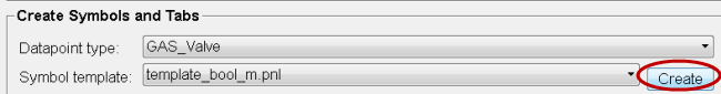
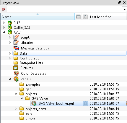
Create a symbol by selecting a Symbol template from the combo box. For this example the template template_bool_m.pnl was selected. The templates are located in the Standard library sub project under Stdlib_[3.18]/panels/objects/STDLIB_template/.
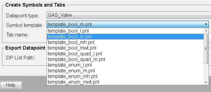
Click on Create.
A symbol is created in you project under Panels/objects/GAS_Valve/GAS_Valve_bool_m.pnl
Import the Stdlib Data Point Types
If you use the "Standard Object Library Setup" Panel of the Standard Library to create a symbol, proceed to step Define a Symbol representation.
-
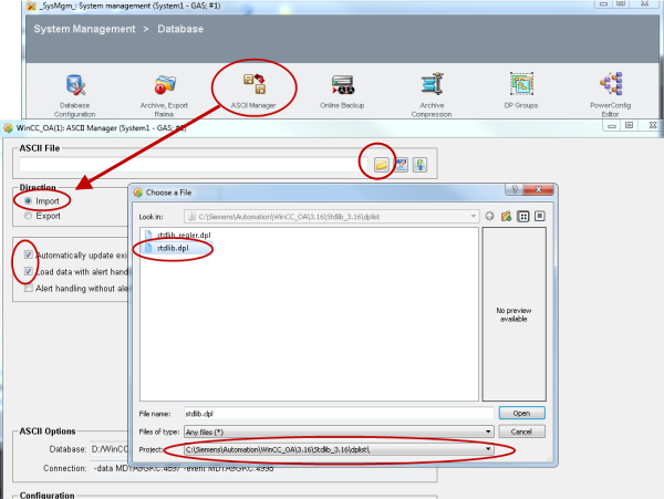
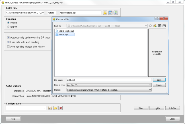
Import the standard library data points via the ASCII manager (System Management -> Database -> ASCII Manager) in order to use the standard object library.
Create Library HOOK Functions
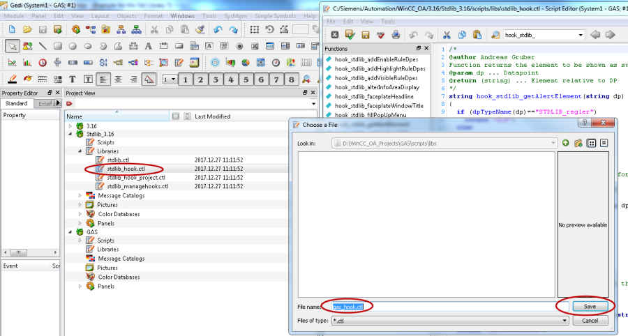
You can find the script stdlib_hook.ctl in the sub project directory \scripts\libs of the Stdlib. This script must be available in every WinCC OA Library project since it contains default settings! The script stdlib_hook.ctl contains the Library HOOK functions. The script stdlib_hook_project.ctl again contains the Project HOOK functions.
The code in these scripts is the default implementation. In order to overwrite the functions, proceed as follows:
-
Copy the stdlib_hook.ctl (wincc_oa_path/Stdlib_3.18/scripts/libs/stdlib_hook.ctl ) by saving it under
<<library name in small letters>_hook.ctl. In this case the name is "gas_hook.ctl":
-
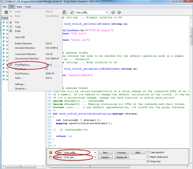
Replace „hook_stdlib_“ by „hook_<library name in small letters>_“. In this case the name hook_gas is being used:
Load Library HOOK Functions
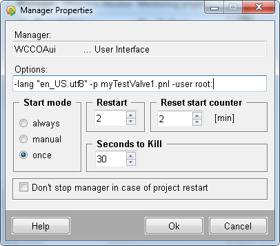
In order to use the HOOK functions in your project, load the functions:
-
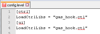
Load library hook functions by creating a config.level file in your project. Load the library functions:
Create a Data Point Type for the Symbol
-
Create a data point type for the symbol. The data point type name must contain the prefix <LIBRARY NAME IN CAPITAL LETTERS>. Specific nodes must be added to the data point type. In this example the nodes: state, alarm, command, para and general are added. The "alarm" node e.g. contains all numerical alert, warning and/or error alert elements. For the description of the nodes - see chapter How to Create Data point Types for the StdLib.
-
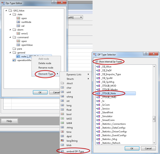
Add text notes on objects as follows: add reference type „_STDLIB_Note“ under „general.note“ :
-
Add Operation mode (local, remote, auto, manual) as follows: add reference type „_STDLIB_OMD“ under „operationMode “
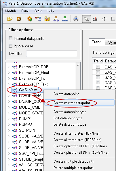
Create a Master Data Point
It is recommended to use master data points wherever several devices of the same type are modeled by using data points.
-
Create a master data point.
-
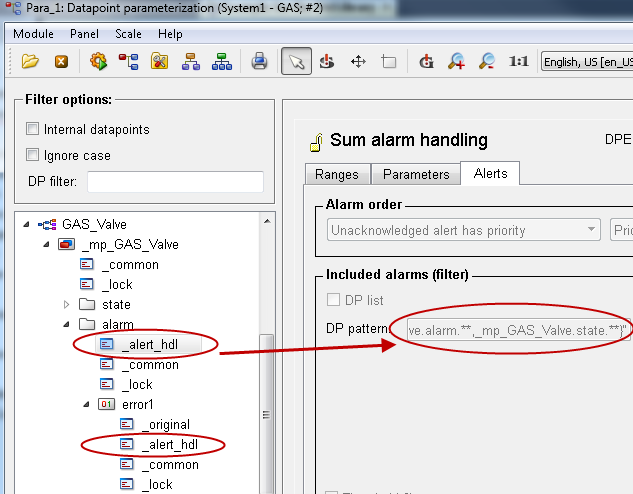
Configure alerts by configuring a sum alert directly on the alert node. Use the pattern "{_mp_GAS_Valve.alarm.**,_mp_GAS_Valve.state.**}".
Select a Symbol Template and Create a Symbol Manually
This example comprises a symbol that displays the two states of a boolean data point. For the symbol a Standard Object Library symbol template is used. Depending on what a symbol should display, a symbol template of a boolean, enum or num data type can be used.
-
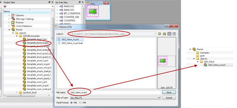
Create symbol by saving the Stdlib/panels/objects/STDLIB_template/template_bool_m.pnl panel under panels/objects/GAS_Valve/GAS_Valve_m.pnl
Do not add the template to a panel via drag&drop. An instance of the symbol (reference) is created via drag&drop.
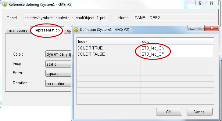
Define a Symbol Representation
The symbol representation specifies the graphical representation for the symbol meaning the colors that are shown via the symbol are defined as well as the data point type and the data point element for the symbol are selected.
-
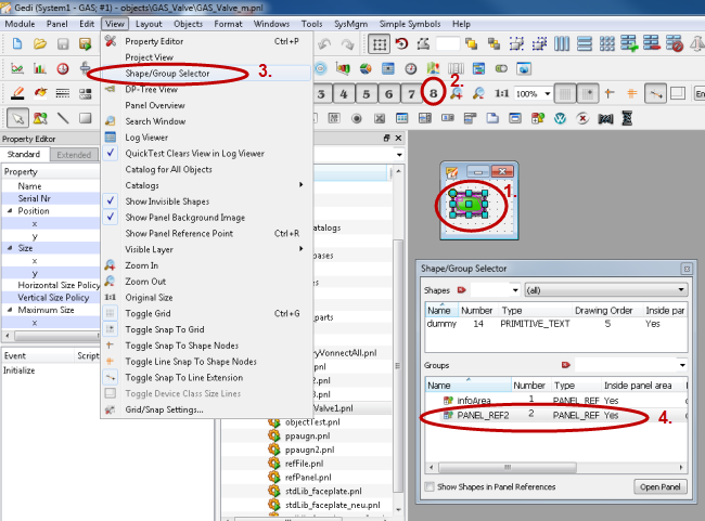
Specify the symbol representation. Select the symbol and open the reference via right-click. Then select an object for your symbol via the View menu of GEDI -> Shape/Group Selector. Note that you have to select the symbol and not the frame. In order to select the green symbol, hide the layer 8 of the symbol.
-
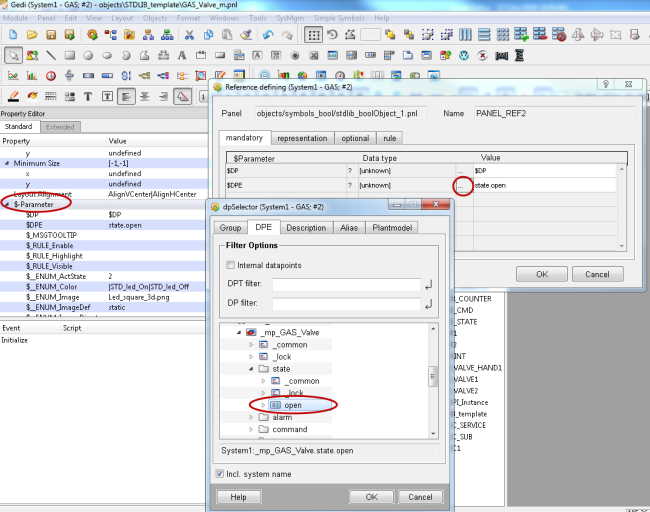
Double-click on the symbol. The reference defining window is opened. Assigne state.open to $DPE.
-
Define colors for 0/1 state of the element "state.open".
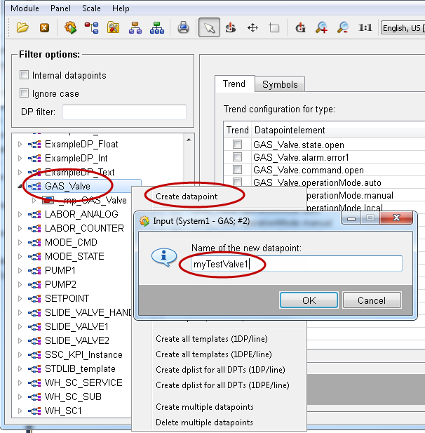
Create Data Points
Create new data points of the data point type created earlier. The data points are created in order to display the symbol.
-
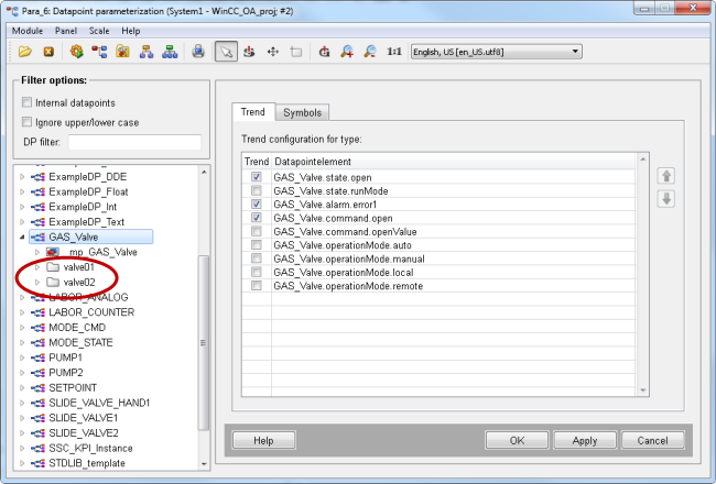
Create new DP instances of the data point type GAS_Valve via the PARA module.
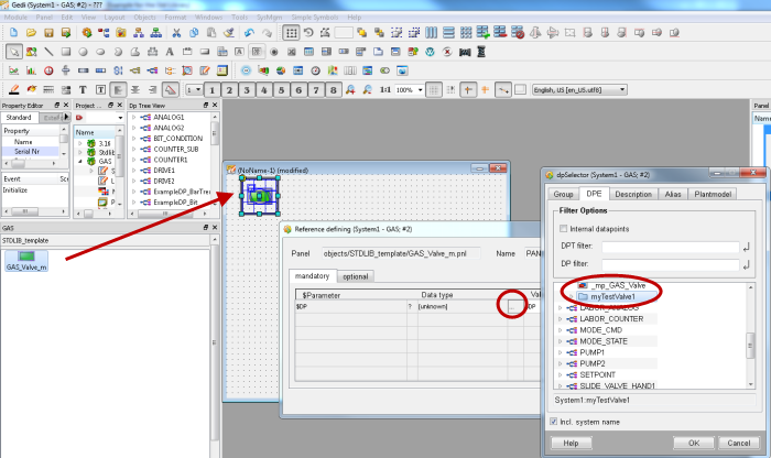
Create a Test Panel and use the Symbol for the Test Panel
Create a test panel in order to display the created symbol.
-
Open the symbol catalog via the View menu of GEDI -.> catalog -> GAS.
-
Drag and Drop "GAS_Valve_m" from the project catalog to the test panel and assign your DP to the dollar parameter (double-click on the symbol).
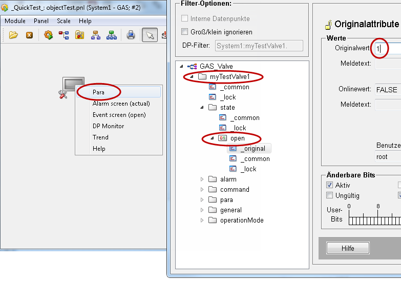
Run the Panel and test the Symbol
Now you can open the panel and test it.
-
Open the panel in the quick test module. Open the PARA module via a right-click and set the value of state.open to 1.
Create a Main Faceplate
A faceplate displays the extended operation dialog of a symbol. This means that in addition to values and states of a data point that are displayed in a symbol, the faceplate panel informs of further values and states. The faceplate can be created either by saving it in the right directory via the "Standard Object Library Setup panel" or manually. This chapter describes both options.
Create a Main Faceplate via the "Standard Object Library Setup panel"
-
To create a faceplate via the "Standard Object Library Setup panel", open the panel via the System Management panel -> Settings -> Stdlib Development Tool
-
Create a data point type by entering the data point name into the text field and clicking on "Create". You can also use an existing type.
-
Select the data point type from the "Datapoint type" combo box.
-
Select a symbol template from the "Symbol template" combo box.
-
Create a main faceplate by entering the name "main" to the text field "Tab name" and by clicking "Create". The faceplate is saved in the project directory /objects_parts/faceplates/[data point type].
-
Proceed with the Step 2 of the Manual Creation of a faceplate.
Create a Main Faceplate Manually
-
Save a new panel under panels/objects_parts/faceplates/GAS_Valve/main.pnl.
-
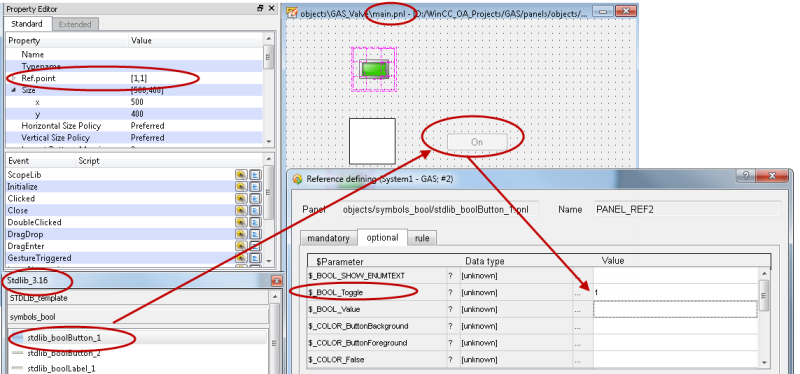
Set the reference point of the panel to x=1, y=1.
-
Open the Stdlib catalog via GEDI menu „View -> catalog -> Stdlib“.
-
From Stdlib catalog Drag&Drop to your main faceplate:
-
-
-
panelSymbols_other/stdlib_objectReference_1.pnl and Symbols_bool/stdlib_boolButton_1.pnl.
-
Double-click the symbol and set the $DPE to the data point element alarm.error1.
-
Double-click the symbol. On the optional tab of the symbol set $_BOOL_Toggle to 1.
-
-
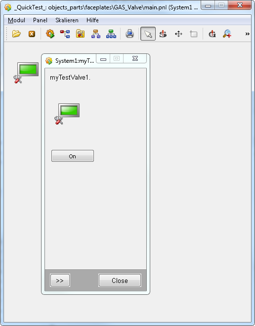
Test the Main Faceplate
The Main faceplate is ready and can be tested.
-
The stdlib_objectReference_1 displays the symbol.
-
The stdlib_boolButton_1 allows to set and reset the alarm.error1.
-
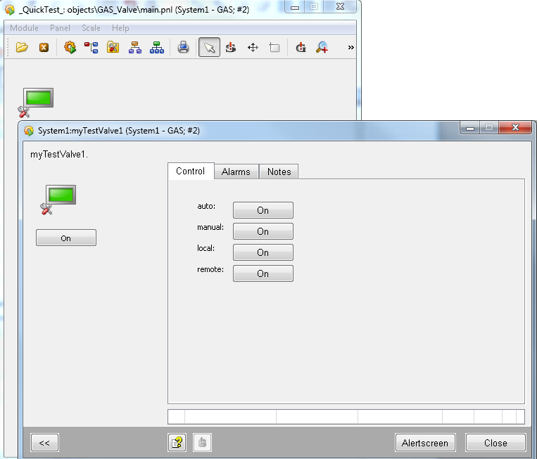
Test the main faceplate.
Add a Control Faceplate Panel
The control faceplate panel can be used to control the faceplate. Different tabs can be added to the panel. In this example the tabs "Control", "Alarms" and "Notes" are added.
- Create a control faceplate panel by
-
-
-
using the "Standard Object Library Setup panel" or
-
-
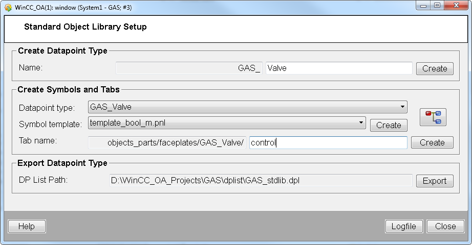
Create a Faceplate via the "Standard Object Library Setup panel"
-
-
-
Open the panel via the System Management -> Settings -> System Management panel -> Settings -> Stdlib Development Tool
-
-
-
-
-
Select the created data point type from the "Datapoint type" combo box and a symbol template from the "Symbol template" combo box. See figure below.
-
Add a tab name e.g. "Control" to the "Tab name" text field. and click on "Create". See figure below.
-
The tab is saved in the project directory /Panels/objects_parts/<data point type name>.
-
You can edit the tab by opening it from the /Panels/objects_parts/<data point type name> directory in GEDI.
-
Proceed to step 3 of the manual example.
-
-
Create a Faceplate by copying the Panel
-
-
-
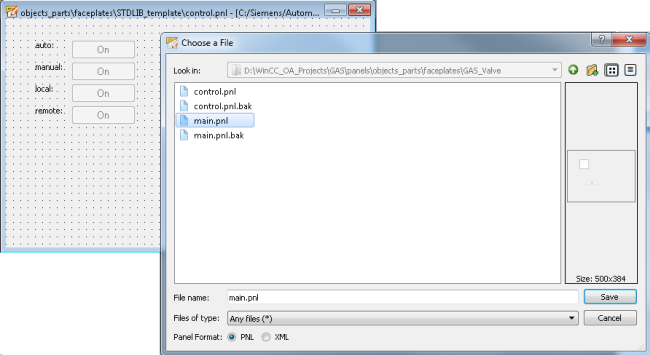
Copy the panel Stdlib/panels/objects_parts/faceplates/STDLIB_template/control.pnl and save it in the directory "GAS_Valve": panels/objects_parts/faceplates/GAS_Valve/control.pnl
-
-
-
The main panel is displayed in the left part of the faceplate. All other panels are listed on the right side in a tab.
-
Since the data point type has the string node „general.note“, the „Notes“ tab is displayed
-
Since the DP has a sum alert handling on the node „alarm“ the „Alarms“ tab is added. For how to create a StdLib data point type and for information about nodes, see chapter How to Create Data point Types for the Standard Object Library.
-
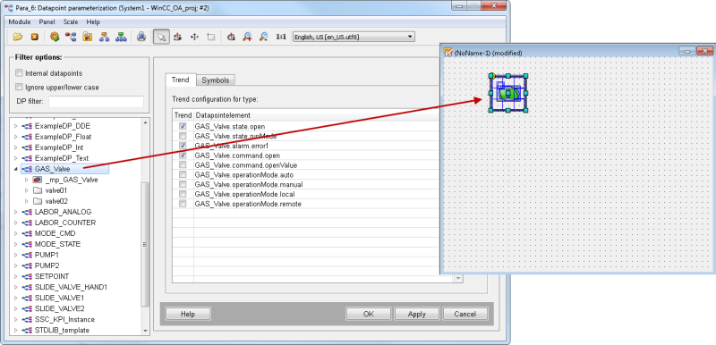
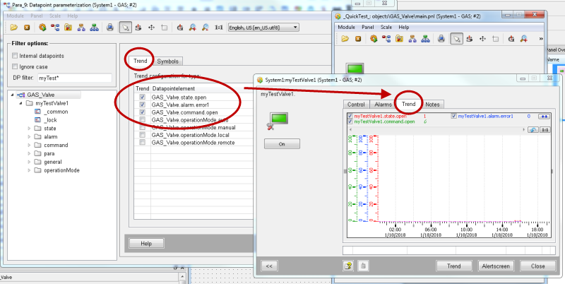
If trend curves are selected on the data point type in the PARA module, a trend is shown at runtime.
Create a new faceplate panel
Another panel facilitates the use of the panel.
-
Create a new faceplate panel: myControl.pnl. If the panel is located in panels/objects_parts/faceplates/GAS_Valve, the panel is only used for the data point type GAS_Valve. If the panel is located in panels/objects_parts/faceplates, it is used in all faceplates (for all data point types).
If the panel is located in panels/objects_parts/faceplates/<DPT_Name>, the panel is only used for the specific data point type. If the panel is located in panels/objects_parts/faceplates, it is used in all faceplates (for all data point types).
Extend the Data Point Type
-
Extend the data point type in PARA module by adding a float DPE in order to set the open value for a valve. Add also an integer node "state.runMode".
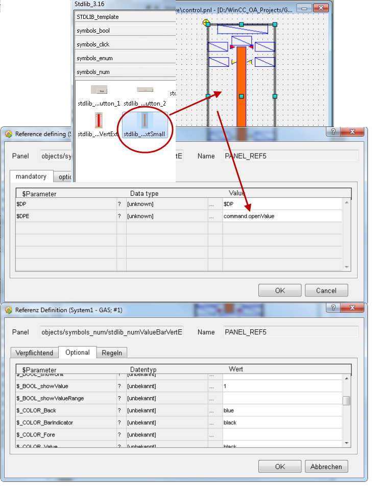
Create a Faceplate Tab
-
Create a faceplate tab by adding elementary symbols for a tab. The elementary symbols display values and are also used to control the modes Run/Off. Add the symbol stdlib_..xtSmall to the panel via Drag&Drop and assign the data point element "command.openValue" to the symbol (doube-click the symbol).
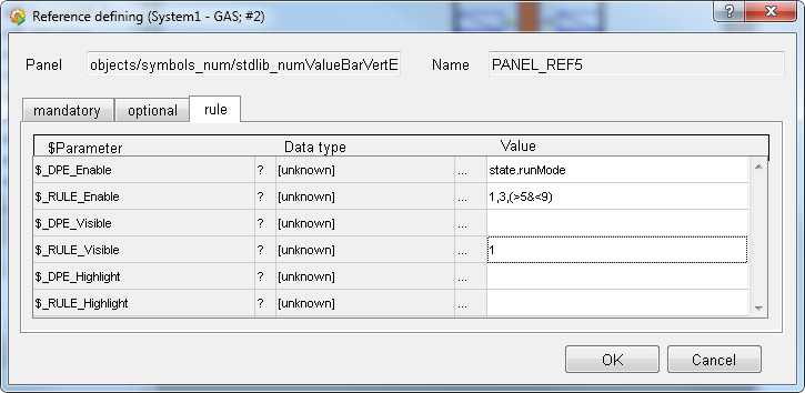
Control the Run Mode
-
The input field will only be enabled for user input. If state.runMode = 1,3 (<5 & <9) <. If the value is 1 or 3 or between 5 and 9. Enter the rule 1,3 (< 5 & <9) into the field $_RULE_Enable
Examples: 1,3 the value needs to be 1 or 3
!4 the value my not be 4
>5&<9 the value must be between 5 and 9
b4 the 4th bit of the value will be used (only integer values).
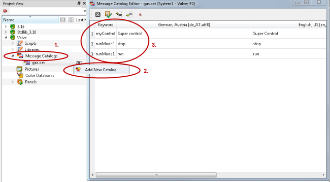
-
Create a message catalog gas.cat via the Project View of the GEDI and add three keywords myControl, runMode0 and runMode1 to it.
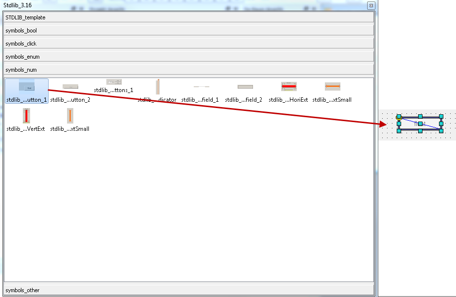
-
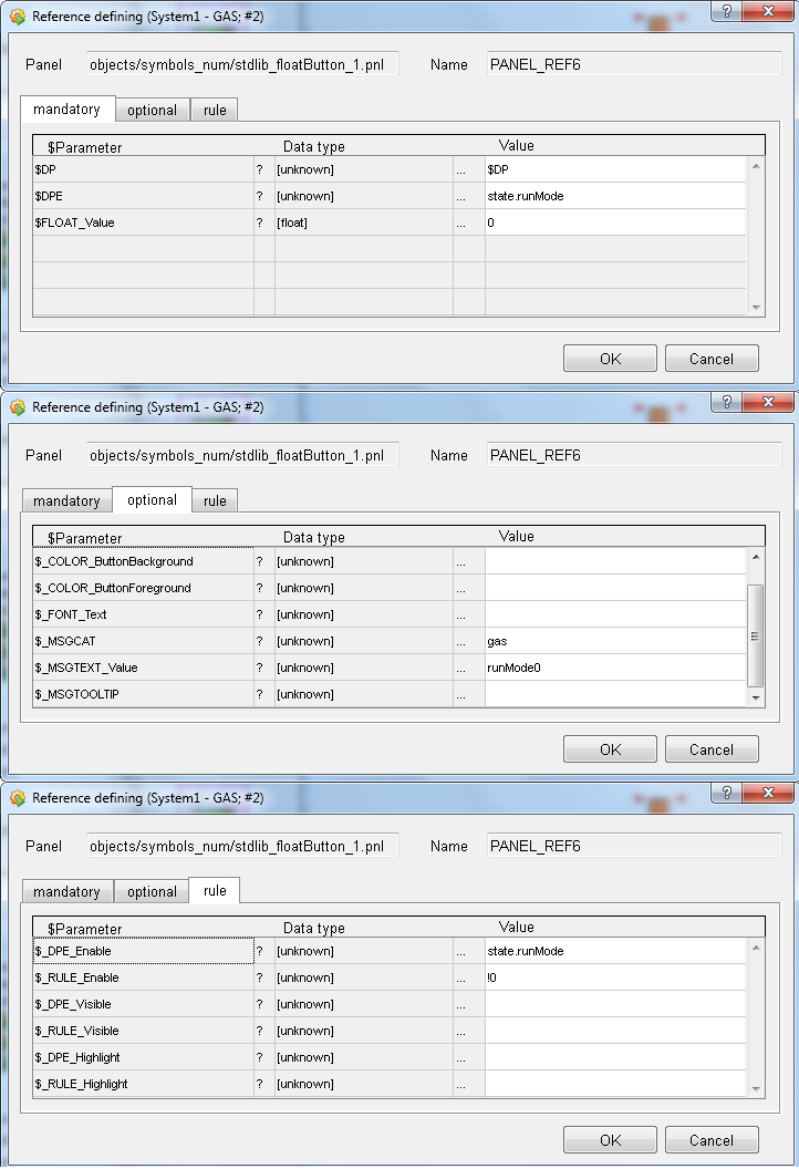
Add a button "stdlib_button_1" from the StdLib_3.18 catalog to the panel. The runMode buttons enable the modes Run/Off and the input field.
-
Set the DPE value of the button to "state.runMode" and the $FLOAT_Value to 0 in order to stop the runMode. On the optional tab, set the $_MSGCAT to gas and $_MSG_TEXT_Value to runMode0 in order to set the text of the button. On the rule tab, set the $_RULE_Enable to !0 and $_DPE_Enable to state.RunMode in order to deactivate the symbol when the value is already 0.
-
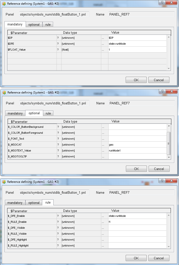
Control the run mode by copying the elementary symbol button and creating a new button. Change the configuration for the new button: $FLOAT_VALUE = 1, $_MSGTEXT_Value = runMode1, $_DPE_Enable to state.RunMode and $_RULE_Enable = !1.
-
The run mode buttons enable/disable the input field.
Execute an Authorization Check in the Library
Execute an Authorization Check in the Library
-
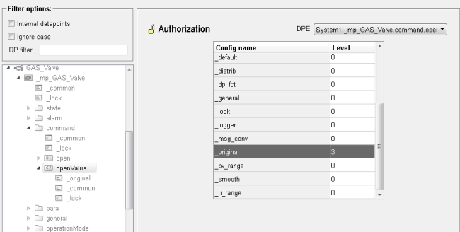
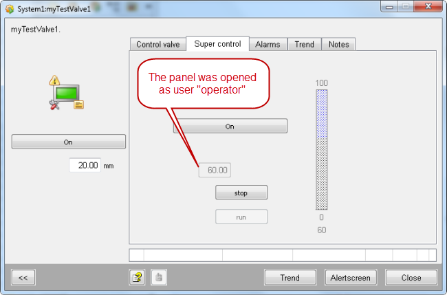
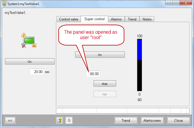
Add an authorization config to the master data point element "command.openValue" via the PARA module. Set the authorization of the _original config to 3. The authorization level 3 is the advanced operator authorization. It permits the execution of commands, explicit setting of replacement values,
input of correction values as well as changes to all value range types.
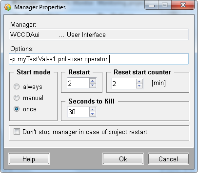
Open the panel as user "operator" and again as user "root".
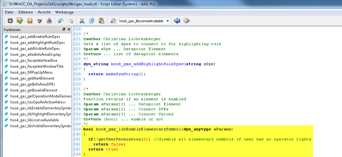
Define Rules for Elementary Symbols
-
Define a rule for all elementary symbols in a library. Change the function hook_<libName>_libEnableElementarySymbol of the gas_hook.ctl. The code deactivates all elementary symbols when a user does not possess operator rights.
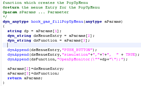
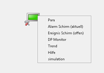
Create a Context Menu Option for a Symbol
-
Add a context menu option for library objects. Therefore, change the function "hook_gas_fillPopUpMenu" of the gas_hook.ctl
Export the created Library for Reuse
-
Export the library for reuse via the "Standard Object Library Setup panel" (see below) or via the ASCII Manager.
Export via "Standard Object Library Setup panel"
-
Open the "Standard Object Library Setup panel" via the System Management Panel-> Settings -> StdLib Development Tool.
-
Click on the "Export" button. The panel exports the project data. The file is saved in "Datapoint Lists"/<project name>_stdlib.dpl.
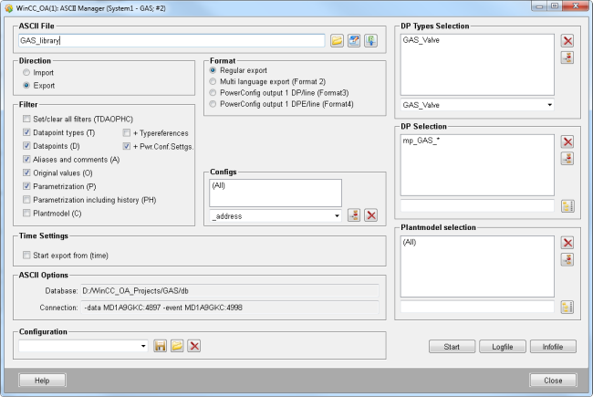
Export via the ASCII Manager
Export the project data via the ASCII manager as follows.
How to use the Library in a Project
-
In order to use the created library in a project, add your own created library and the StdLib library to your project as sub projects. Note that the order must be as shown in the figure below
-
Import the stdlib data point list.
-
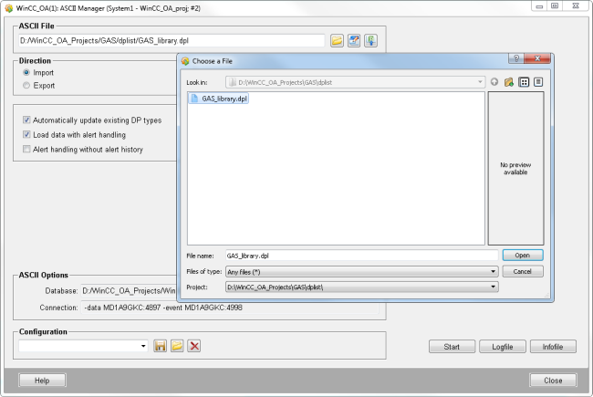
Import the GAS_library data point list.
-
Create new data points via PARA module:
-
Create a panel via GEDI. Add the data point type GAS_Valve to your panel via drag&drop: