Creating an operating-time/operations counter

The following instructions provide simple examples of how to create an operating-time counter and an operations counter in WinCC OA.

Creating an operating-time counter

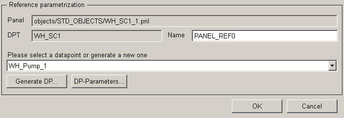
The symbol catalog in the GEDI explains how to create a WH in WinCC OA. When you insert the WH/SC symbol on a panel, the reference editor is displayed.
Figure 1. Reference editor
Here you can select an existing data point from the combo box for the WH (e.g.: a data point for a WH/SC created from the System management panel) or create a new one. Left-click "Generate DP..." (to create a new DP) to open the panel for creating a DP for the WH/SC (cf. operating-time/operations counter).

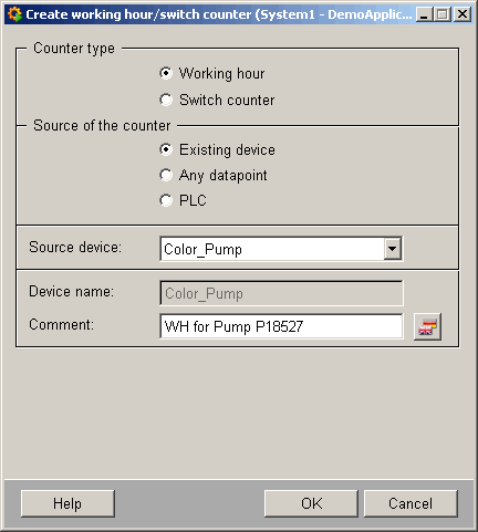
Selecting the counter type: operating-time counter

Setting the counter source:

  • Existing device: This setting is used to select an existing device in WinCC OA from the "Source device" combo box. The device name is grayed out. You can enter a custom text in the "Description" text box to be used internally in WinCC OA. The source data point element ".state.on" is automatically allocated when you create a WH.

  • Any data point: This setting allows the user to select the source data point element for the WH using the data point selector. You can also specify any device name and description. (Start of counting is automatically identified depending on the data point element; for a binary value == TRUE or for an analog value <> 0.)

  • PLC: The source data point element (.value.plcCounter) is grayed out because the PLC writes to this data point element for counting and it may not be edited. Again, you can also specify any device name and description. For PLC counting, you can also specify the factor, overflow and reset threshold. The factor determines the increment value for the PLC response (e.g. factor 1 means the value is incremented by one). Overflow specifies a maximum value that causes the WH to be reset to zero if exceeded. The reset threshold shows the user whether the value (overflow) is exceeded or whether the counter has counted down (e.g. WH is at 9999998; after a while it displays 9999994, so it must have been counted down). You can edit these settings on the Edit parameters panel.

Figure 2. Setting the factor, overflow and reset threshold

Example: Create a WH

Create a WH for a device (pump) called "P18527" (data point "P18527" of data point type "PUMP1") using the symbol catalog in GEDI.

Procedure:

  1. Drag the symbol into a new panel. (with display of description)

  2. Create the DP for the WH using the reference configuration panel. Press "Generate DP...".

  3. Make the following settings:

  1. Press "Create" to generate the data point for the WH.

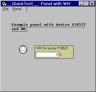
  2. The panel might look like this:

Operating-time counter created for pump "P18527".

Creating an operations counter

The procedure for creating an SC is the same as for a WH. (cf. Creating an operating-time counter)
The difference when creating an SC is that there is one counter source option less on the panel for creating a DP for WH/SC (PLC counting). The reason is that WinCC OA internally evaluates a device's operations better than a PLC count.

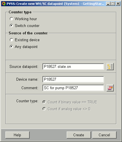
Selecting the counter type: Operations counter

Setting the counter source:

  • Existing device: This setting is used to select an existing device in WinCC OA from the "Source device" combo box. The device name is grayed out. You can enter a custom text in the "Description" text box to be used internally in WinCC OA. The source data point element ".state.on" is automatically allocated when you create an SC.

  • Any data point: This setting allows the user to select the source data point element for the SC using the data point selector. You can also specify any device name and description. (Start of counting is automatically identified depending on the data point element; for a binary value == TRUE or for an analog value <> 0.)

Example: Create a SC

Create an SC for any data point element (e.g.: state.on - counts one operation whenever the device switches to "ON" state) using the symbol catalog in GEDI. (For this example we will use the device P18527 as in the example of how to create a WH - cf. Example: Create a WH)

Procedure:

  1. Drag the symbol for an SC into a new panel. (with display of description)

  2. Create the DP for the SC using the reference configuration panel. Press "Generate DP...".

  3. Make the following settings:

  1. Press "Create" to generate the data point for the SC.

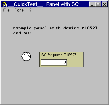
  2. The panel might look like this:

Operations counter created for pump "P18527".
The counter for operations is not incremented immediately, but it has a cycle time of one hour (i.e. the value for the operations is displayed after this period in the panel).