Example for creating simulation data
The following example shows you how to run the simulator. In this example the data points ExampleDP_AlertHdl1 and Hdl2 as well as the data point ExampleDP_Arg1 are used. This means that bit and float values are simulated.
-
Open an arbitrary ASCII file editor and create a simulation file with the following entries.
Figure 1. Simulation file Sim.txt 
Save the file directly in the <proj_path> e.g. in my_proj (not in a particular directory) .
The file is divided into two blocks: the periphery list, where the objects are declared, followed by the section where the values are entered and the times specified for transferring the values (notification list). Any name can be chosen for the file, although this alphanumeric character combination cannot contain spaces.
The file begins with the object declaration (data points). The first number you can see in the figure above is the object type. In this example the number is either 1 or 8. 1 means bit and that the data point is of type boolean. 8 means that the data point is of type float. Next to the types you can see the object names listed. These names have to be used later when adding address configs. The declaration list has to end with the number -99.
After the declaration values are assigned to the objects. Since no arrays are used in this example the subindex is 0 (subindex is the first number after the number -99). If you use arrays the first element is the element number 1 (and the subindex is 1), the second the element number 2 etc.
Enter the object names into the secondcolumn. Enter the data types of the values, which are assigned, into the third column. Enter the values, which are assigned to the objects , into the fourth column. The fifth column (seconds) together with the sixth column (milliseconds) give the wait time before processing the next line of the file.
Note that when you have an English operating system the float values of the simulation file have to be separated by a dot (not a comma).
-
Start the simulation file from the console. Double-click with the left mouse button on the simulation manager and define the following start option:
-t C:/<proj_path>/Sim.txtso for your own project e.g.
-t C:/WinCC_OA_Proj_projects/proj_new/Sim.txt -
Add an address config for the data points (ExampleDP_Arg1, ExampleDP_AlertHdl1 and ExampleDP_AlertHdl2 ) that were used in the simulation file and configure the periphery simulation.
If the address has more than 32 characters, the simulation file will not be run.
Figure 2. Peripheral config: settings for the simulator 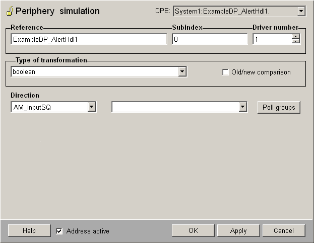
Enter the data point name, which was used when declaring the object name (ExampleDP_Arg1, ExampleDP_AlertHdl1 and AlertHdl2) in the periphery list, into the reference field. The subindex is 0 since no arrays are used in this example. The driver number depends on the number that was used when the simulation file was started from the console. In this example the manager number 1 was used and the driver number is 1. Select the type boolean for the data points ExampleDP_AlertHdl1 and AlertHdl2 and type floating decimal point for the data point ExampleDP_Arg1 from the type of transformation combo box. Thus 3 configs are added to three different data points. As already described the settings for the two data points ExampleDP_AlertHdl1 and AlertHdl2 are equal except for the reference.
-
Start the simulation via the internal data point _Simulator_1. Set the value of the signal element to TRUE (1).
Figure 3. _Simulator_1 data point for starting the simulation 
The simulation is started. You can see the steps in the log viewer. Open the used data points (ExampleDP_AlertHdl1, ExampleDP_AlertHdl2 and ExampleDP_Arg1) and you see how the data point values are changed.
Figure 4. Log viewer with the simulator output