Terms and special features
Addressing
The Addressing type used by SAT is source addressing, i.e. each message contains the address of where it was generated.
An error data point is sent to the Event Manager for unknown message formats and if messages are received from addresses not recognized in WinCC OA (no peripheral addresses was configured). The error is output on stderr if an arbitrary debug flag (e.g. -dbg 3) is given.
The address in SSI messages is made up of the following elements:
- Module number
-
Value range 0 to 29
20 to 29 is reserved for the VSR
always 255 for system messages
- Data type
-
Value range 1 to 31
0 for system messages
- Component number
-
Value range 1 to 254
the target address 255 can also occur in system messages; this means "to all" components
- Region number
-
Value range 0 to 250
- Subaddress
-
always set to 0 for messages from host to SK 1703
for incoming messages from the SK 1703 it currently equals the data type
if the data type is 0 it is set to 255
The subaddress meaning can be configured in the driver (see entry in the configuration file: "subAdrInUse"). Since the subaddress is currently irrelevant to the remote system, it is always set to 0 for incoming data messages (and in the peripheral address of the data point in WinCC OA).
- Value number
-
Value range 0 to 254
always 255 for system messages
Message status
The message status contains information on the transmission status. The following bits are defined:
- DV - Data loss
-
set if it is the last valid message before identified data loss, e.g. because transmit buffer has overflowed.
an Error data point is sent to the Event Manager if this bit is set.
- GA - General query
-
specifies whether the message was generated in response to a general query
one can set via the internal data point of the general driver whether GA data should receive special treatment (filter mode using drvSmoothMode - see entry in the configuration file), before it is forwarded to the Event Manager.
mapped onto the GA bit of the original value config in WinCC OA
- H - High priority bit
-
indicates that it is high priority data
this bit can be mapped onto a user bit ("map
UserBit" entry in the configuration file)
- NEZ - not real time
-
the associated time information is erroneous (only for real-time data)
the time information is replaced by the host time in the driver
this bit can be mapped onto a user bit ("mapUserBit" entry in the configuration file)
If the GA bit and S bit are set at the same time, then a value change occurred during the GA. If both are 0 then the data is cyclically transmitted data.
- NS - not sorted
-
set if the data is unsorted real-time data
not set if the data is non-real-time data or if it is not correctly sorted chronologically.
this bit can be mapped onto a user bit ("mapUserBit" entry in the configuration file)
- S - Spontaneous bit
-
set when there is a spontaneous value change
this bit can be mapped onto a user bit ("mapUserBit" entry in the configuration file)
- T - Test mode
-
indicates that the message was only generated for test purposes
if the bit is set then the message is currently discarded.
Data status
The data status provides information on the status of the sent data:
- A - Manual disable
-
this bit can be mapped onto a user bit ("mapUserBit" entry in the configuration file)
- E - Replacement value
-
this bit can be mapped onto a user bit ("mapUserBit" entry in the configuration file)
- I - Invalid
-
the transmitted value is invalid because of an error
for 16 individual messages it is only set if all are invalid
the invalid bit is mapped onto the original value config in WinCC OA
- V - Availability
-
set when reduced availability
this bit can be mapped onto a user bit ("mapUserBit" entry in the configuration file)
EZ and NEZ messages
In the SAT system one can configure whether both a real-time (EZ) message and a non-real-time (NEZ) message are generated for each event. Non-real-time messages are not sorted and arrive more quickly than real-time messages. In WinCC OA, incoming external messages with and without a time stamp can be configured to two different data points. If the user only sets one data point for one of the two data streams, then the messages arriving in the other stream are automatically discarded by the driver. No error data point is sent in this case, although a message is output in debug mode indicating a possible configuration error. An error data point is only generated if there is neither an EZ nor a NEZ setting for an incoming message. In the send direction the driver adds its own system time when generating EZ messages.
Peripheral address in WinCC OA
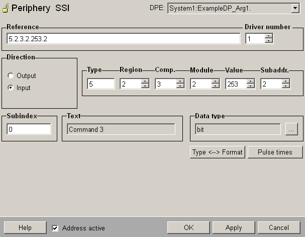
The peripheral address in WinCC OA is held in its own config. A separate hub config containing just the driver number is used to assign a data point to a driver and thus to an area of the system accessible from a particular remote head. At start-up the driver uses this number to register an interest in the data points that it is concerned with. If a hub config has not been created for a data point with a peripheral address, then this data point is assigned to driver number 1. The peripheral address config assigns a hardware address to a data point name; this address is coded as a character string.

This address has the following structure for SSI messages. The Option "Address active" is selected. An inactive address means, that there is no connection to the PLC (see Reference tables).
The address contains six items of information separated by ".":
- Data type
- Region number
- Component number
- Module number
- Value number
- Subaddress
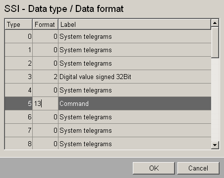
Each piece of the address consists of a number (three figures maximum without leading zero). The data type is the data type configured for the expected message format. The subaddress should be 0 if the subAdrInUse entry in the configuration file is not set to "Yes". The data-type to data-format assignments are specified in the data point _SSI_DaDf_Table, which has 32 sheets for the different data types (0 to 31). Undefined data types have the initial value -1.

The address of a data point with an integer data format (data format 2) is shown in the example. The project-related data type 11 is assigned to the integer format. The data point is assigned to the peripheral device with module number 20, value number 30 of component 21 in region 0. The correct address string then reads:
11.0.21.20.30.0In addition for more complex data types (such as 16 separate messages), the subaddress of the peripheral address config can be set as an extra parameter for each element. The subaddress meaning is described under the individual message formats.


